Antenna having controllable emission of radiation

Inactive Publication Date: 2007-01-11
WIVENHOE TECH LTD
View PDF7 Cites 4 Cited by
  • Summary
  • Abstract
  • Description
  • Claims
  • Application Information

AI Technical Summary

Benefits of technology

[0012] The use of at least one low loss radio frequency (RF) switch (for example micro electromechanical switch (MEM) or PIN diode) will introduce phase shifts in the signal travelling on the transmission element by shorting or open-circuiting the element. This has the effect of changing the radiation pattern of the antenna. Hence the radiation pattern can be made adaptive by using multiple switches.
[0013] Advantageously the dielectric constant of one or both of the dielectric material layers is variable. Variation of the dielectric constant can be by means of an applied d-c voltage which causes a change in the dielectric constant of the dielectric material. Since the guided wavelength along the spiral arm is dependant on the value of the dielectric constant, changing the dielectric constant causes a change in the angle of the emitted beam. Particula

Problems solved by technology

Whatever the type of information being communicated, the problem remains of enabling a device to continue in contact with a transmission/reception t

Method used


Image

  • Antenna having controllable emission of radiation
  • Antenna having controllable emission of radiation
  • Antenna having controllable emission of radiation

Examples


Example

[0030] The following example is one embodiment of the invention. It will of course be understood that there are a number of ways of incorporating the invention which do not depart from the inventive concept.

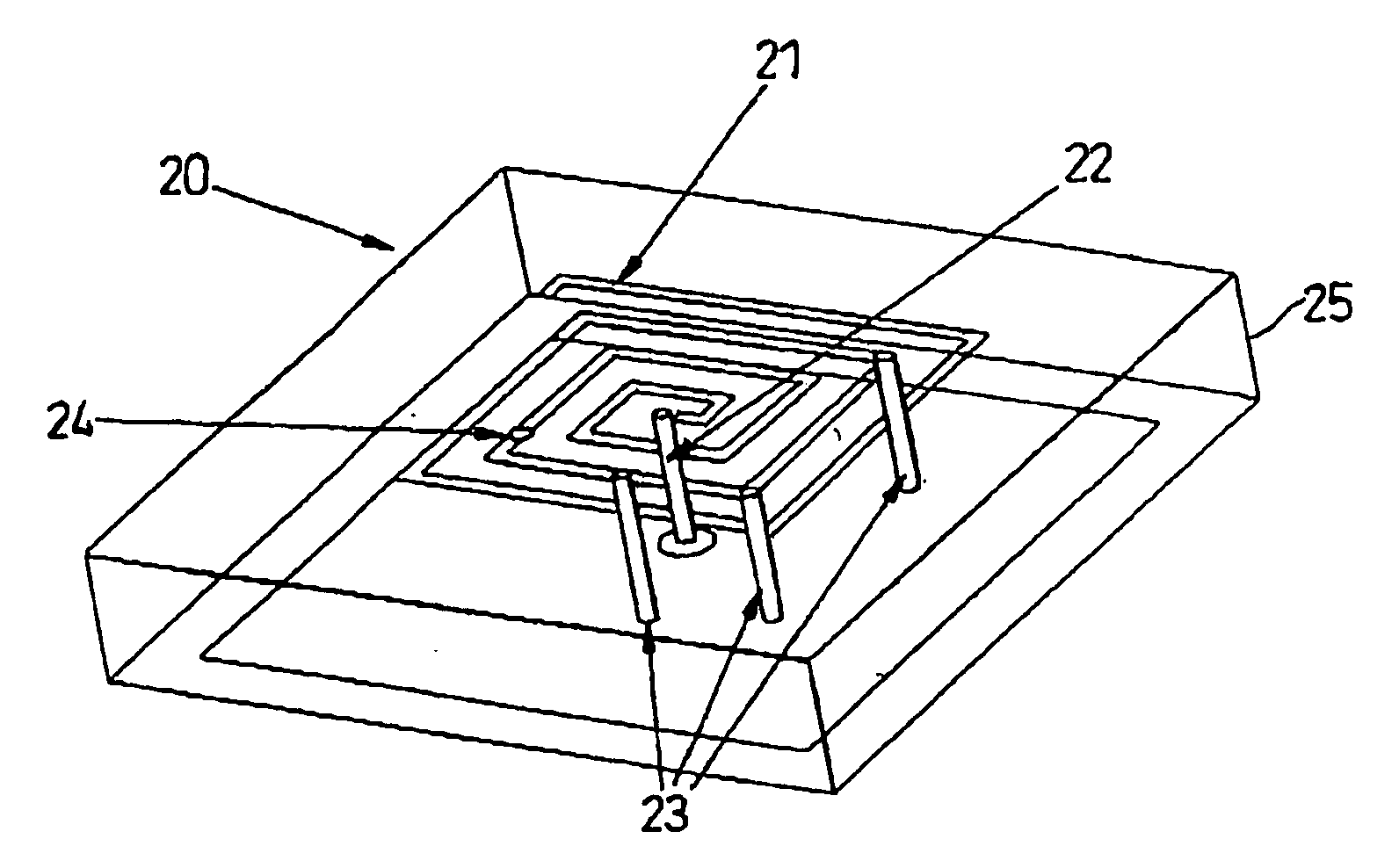
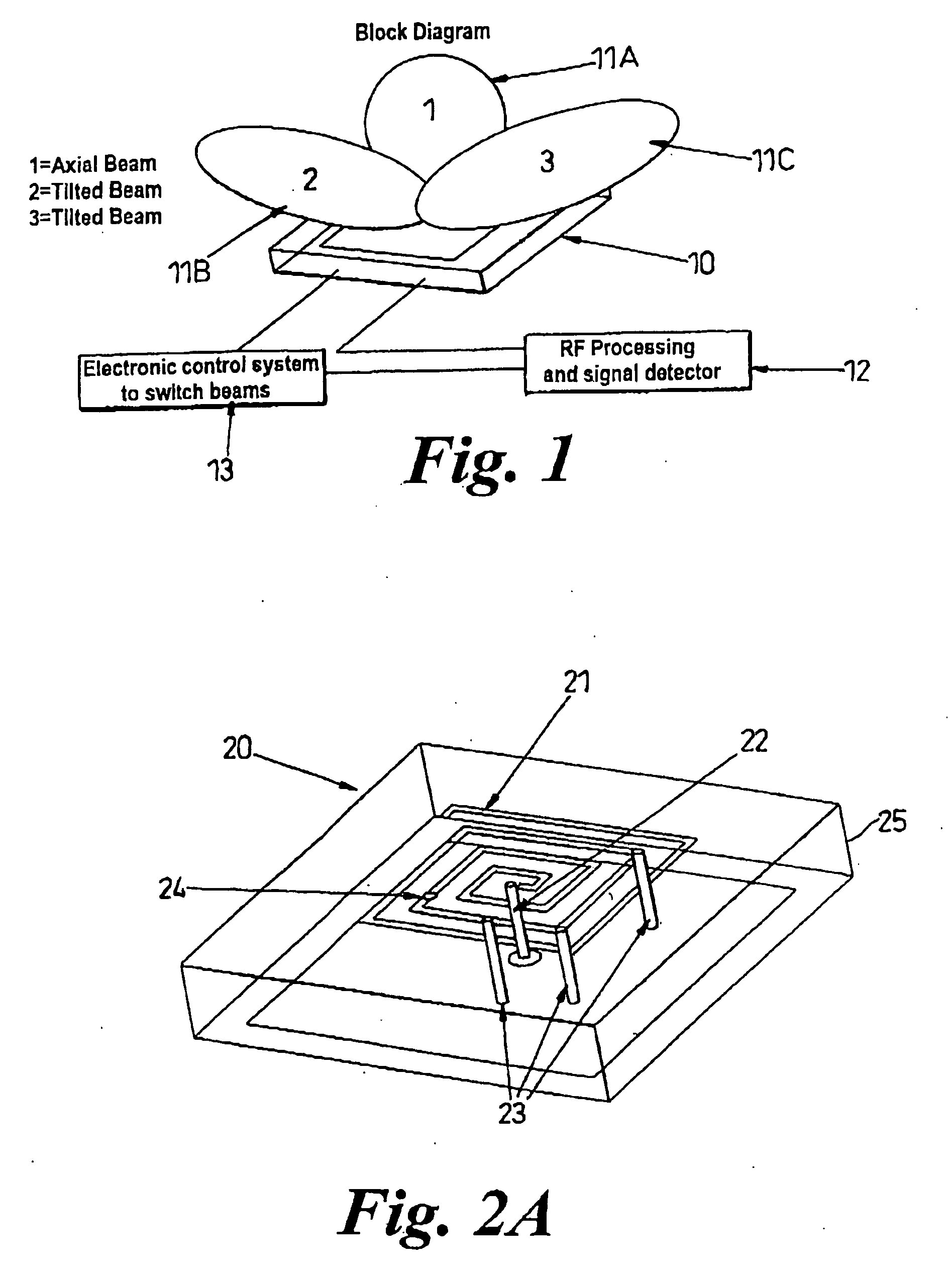
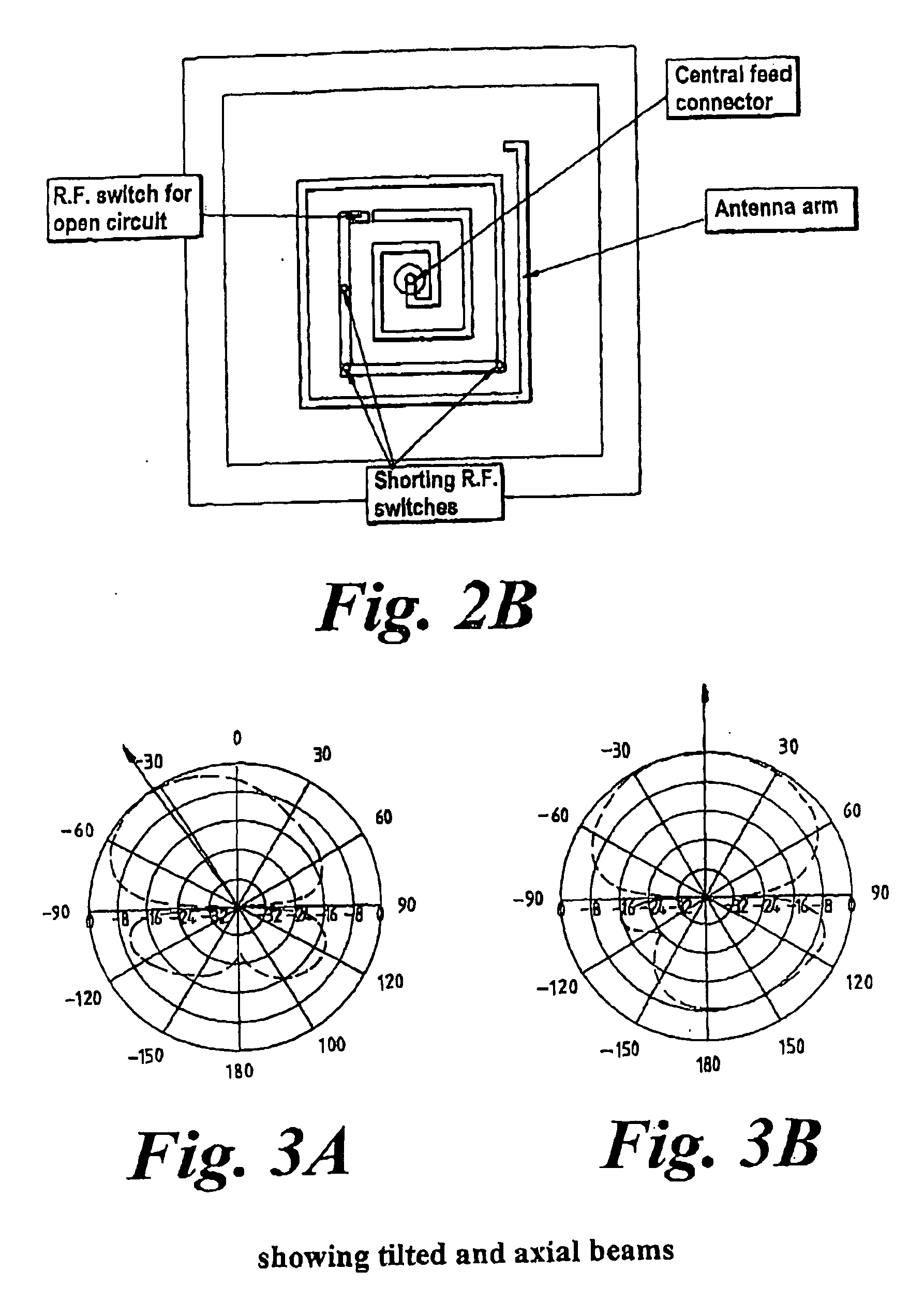
[0031] In FIG. 1, an antenna 10 which emits a signal in the form of a beam of electromagnetic radiation. The beam is capable of carrying sufficient information for a decoding device to reproduce sound, text or visual images. The beams 11A,B,C are inclined at different angles relative to each other. The angle of the beam is variable and thus beams 11A,B,C are just illustrative examples. This feature maximises the possibility of the element either transmitting to a tower or alternatively receiving a message therefrom.

[0032] In determining the angle of the beam to be used, a processing and signal strength detector 12 monitors the strength. Should the detector 12 determine the need to transmit using a different beam 11, the detector 12 sends a signal to a circuit 13 which controls ...


PUM


Abstract

An antenna (10) suitable for a mobile telephone or other such communication device has a transmission element (21) to transmit and receive an electromagnetic radiation pattern. The transmission element (21) is supported on a layer or layers (25) of dielectric material, control over the orientation of a radiation pattern to be transmitted or received being maintained electronically. The transmission element (21) includes at least one loop and is often in a spiral configuration. Switches (23, 24) in the form of a microelectromechanical switch or a PIN diode, capable of short or open circuiting the element (21), allow the orientation of the radiation pattern to be altered. The dielectric constant of the dielectric material (25) is variable, again affecting the orientation.

Description

FIELD OF THE INVENTION [0001] The present invention relates to an antenna with improved capability in locking onto a signal. The antenna is particularly suitable for use as part of a mobile telephone or any wireless device. BACKGROUND TO THE INVENTION [0002] The growth in the market for hand-held communication devices, not physically connected to a communication land line has, in recent years, been consistent and large. In particular, mobile telephones are now not only capable of allowing voice communication but also the transmission of moving images, virtually in real time. [0003] As there is no physical connection between a device and a land line, communication or information is transmitted by means of electromagnetic radiation signals. The means to transmit said information is usually an antenna attached to a device. For a device to transmit information, a low power signal is emitted from the device via the antenna. The signal is received by a tower which forwards the signal on. ...

Claims


Application Information

Patent Timeline
IPC IPC(8): H01Q1/36H01Q1/38H01Q3/24H01Q3/44H01Q9/27H01Q9/40
CPCH01Q1/38H01Q3/247H01Q9/40H01Q9/27H01Q3/44
Inventor MEHTA, AMITMIRSHEKAR, DARIUSH
Owner WIVENHOE TECH LTD
Why Eureka
Try Eureka