Syringe Stopper and Plunger Rod Arrangement for a Syringe Assembly

a technology of syringe and plunger rod, which is applied in the direction of intravenous devices, medical devices, other medical devices, etc., can solve the problems of increasing bulk material costs, manufacturing costs, and leaching of toxins into syringe medication, and achieving the effects of reducing bulk material costs, manufacturing costs, and leaching of toxins

Active Publication Date: 2021-02-11
BECTON DICKINSON & CO
View PDF5 Cites 1 Cited by
  • Summary
  • Abstract
  • Description
  • Claims
  • Application Information

AI Technical Summary

Benefits of technology

[0010]It is an object of the invention to provide an improved syringe stopper and plunger rod arrangement for use with thermal plastic elastomers. This improved arrangement is configured to better tolerate the high temperatures experienced by the arrangement during an autoclave sterilization process for increased syringe sealing performance robustness. The new arrangement makes it possible to use lower compression set performance materials such as thermal plastic elastomer resins for the syringe stopper, while still satisfying sterility, leakage, and other performance requirements necessary for a syringe. Utilizing thermal plastic elastomer resins for the syringe stopper significantly decreases bulk material costs, manufacturing costs, and leachable toxins to the syringe medication, as compared to traditional vulcanized rubber syringe stoppers.
[0011]To incorporate thermal plastic elastomers into syringe stoppers for use with autoclave syringes, the stopper stress concentrations can be reduced in order to reduce material yielding and increase sealing pressure. Further, the plunger rod side loading can be transferred directly from the plunger rod to the syringe barrel, thereby reducing asymmetric stopper deflection induced loading / leakage.
[0012]The stopper seal stress concentrations in the stopper ribs can be reduced to minimize localized stopper rib yielding during high temperature autoclave sterilization processing. This stress concentration reduction can be accomplished by balancing the stopper rib contact area with the internal structural features of the stopper and the overall barrel interference fit. The fluid sealing robustness can be increased by using fluid pressure during infusion with stopper cone internal support features. These support features allow the stopper cone to marginally collapse or slightly bend when the syringe fluid is under pressure. The cone bending causes the stopper cone base to apply radial loading on the stopper ribs, which increases the sealing contact pressure proportional to the syringe fluid pressure.
[0013]Angular misalignment of the stopper when the plunger rod is subjected to side loading can also be reduced by incorporating design features to limit the angular misalignment between the plunger rod and the barrel. The angular misalignment of the plunger rod can be further reduced by incorporating angular flex plunger rod design features between the plunger rod and the stopper. The angular flex features allow the plunger rod to barrel angular misalignment loading to be decoupled or significantly reduced at the plunger rod to stopper interface.

Problems solved by technology

Utilizing thermal plastic elastomer resins for the syringe stopper significantly decreases bulk material costs, manufacturing costs, and leachable toxins to the syringe medication, as compared to traditional vulcanized rubber syringe stoppers.

Method used


Image

  • Syringe Stopper and Plunger Rod Arrangement for a Syringe Assembly
  • Syringe Stopper and Plunger Rod Arrangement for a Syringe Assembly
  • Syringe Stopper and Plunger Rod Arrangement for a Syringe Assembly

Examples


Embodiment Construction

[0023]For purposes of the description hereinafter, the terms “upper”, “lower”, “right”, “left”, “vertical”, “horizontal”, “up”, “down”, “lateral”, “longitudinal”, and derivatives thereof, shall relate to the invention as it is oriented in the drawing figures. However, it is to be understood that the invention may assume various alternative variations, except where expressly specified to the contrary. It is also to be understood that the specific devices illustrated in the attached drawings, and described in the following specification, are simply exemplary aspects of the invention. Hence, specific dimensions and other physical characteristics related to the aspects disclosed herein are not to be considered as limiting.

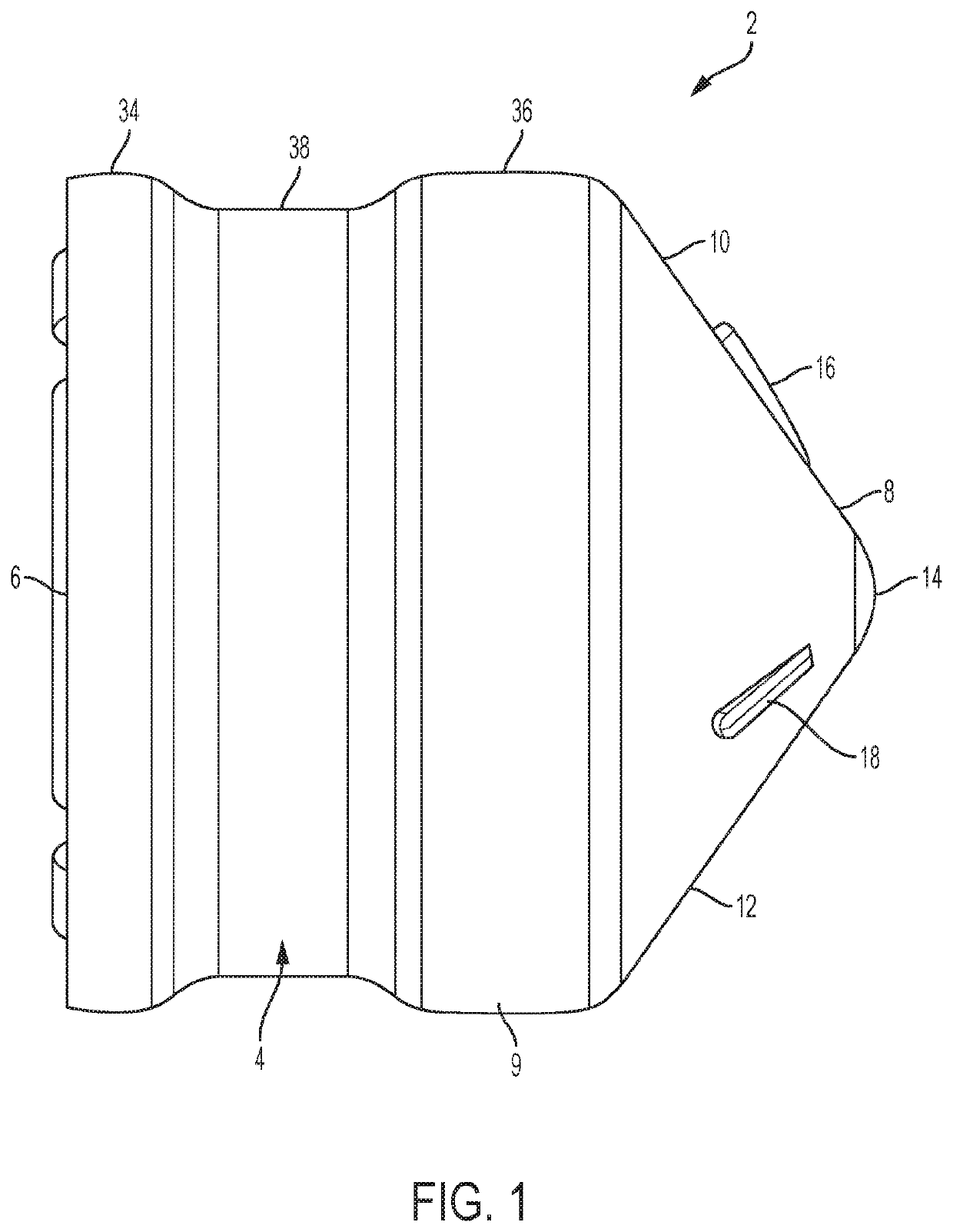
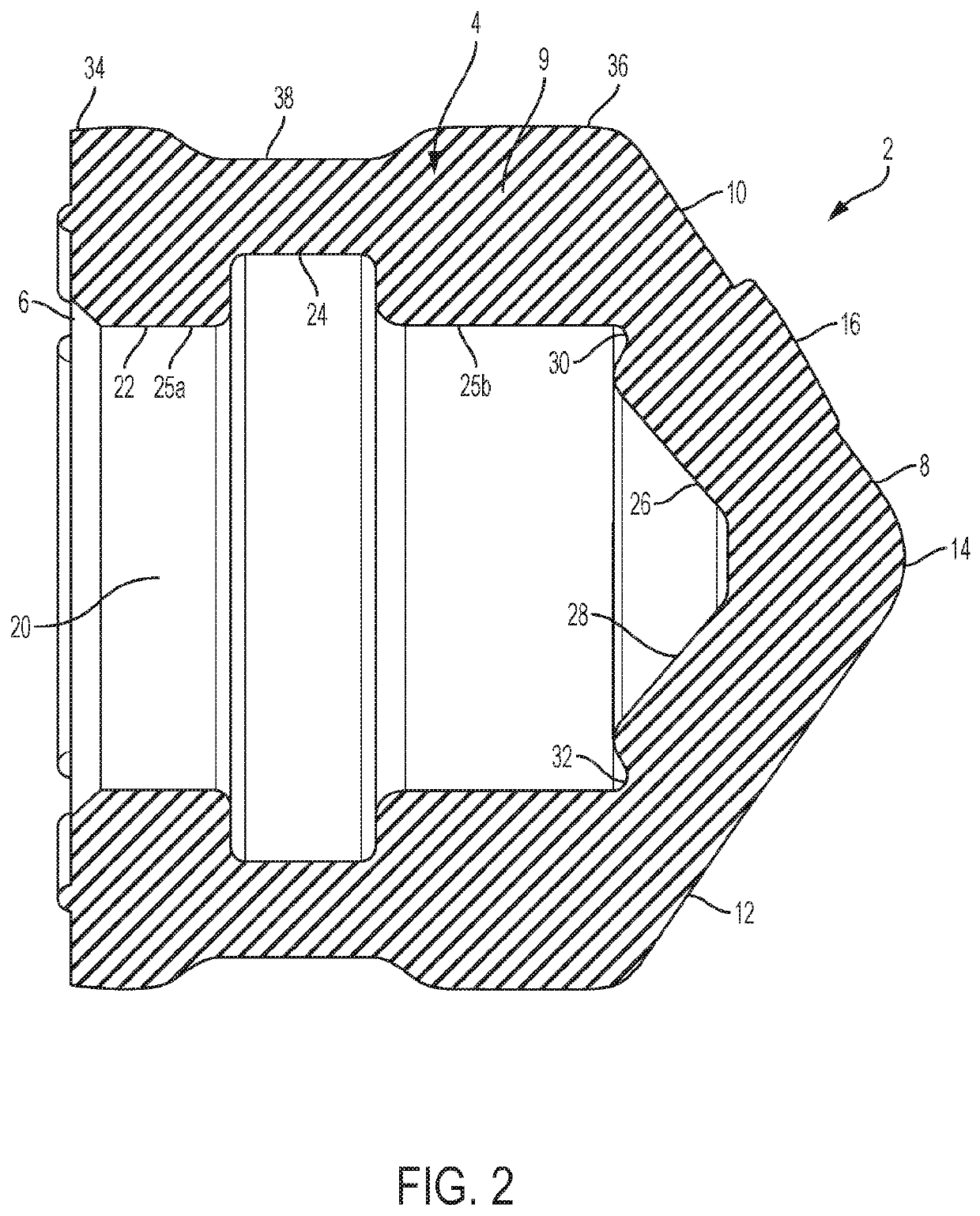
[0024]With references to FIGS. 1 and 2, a first aspect of the stopper 2 includes a main body portion 4 defining an open rearward end 6 configured to receive a plunger rod and a closed front end 8 that forms a flexible roof. In one aspect, the stopper 2 is made of a the...


PUM


Abstract

A syringe assembly includes a substantially cylindrical syringe barrel including a fluid dispensing end, an open end, and at least one protrusion adjacent the open end, the at least one protrusion projecting inwardly from an inner surface of the syringe barrel, a stopper configured to be received within the open end of the syringe barrel, and a plunger rod having a plunger rod body extending along a longitudinal axis from a proximal end to a distal end and at least one support disk provided on the distal end thereof. The support disk on the plunger rod is configured to bear against the protrusion of the syringe barrel upon misalignment of the plunger rod in the syringe barrel.

Description

CROSS-REFERENCE TO RELATED APPLICATION[0001]The present application claims priority to U.S. Provisional Application Ser. No. 62 / 645,353, entitled “Syringe Stopper and Plunger Rod Arrangement for a Syringe Assembly”, filed Mar. 20, 2018, which is incorporated herein by reference in its entirety.BACKGROUND OF THE INVENTIONField of the Invention[0002]The invention relates, in general, to a stopper assembly for use with a syringe and, more particularly, a stopper and plunger rod arrangement for use with a syringe.Description of Related Art[0003]Current syringe designs can typically be categorized as two-piece syringes or three-piece syringes. A typical three-piece syringe includes a tubular barrel having an access opening formed at one end, and a smaller discharge opening formed at the opposing end. The lead end of an elongated plunger is received within the access opening of the barrel so as to be slidable within the barrel. Attached to the lead end of the plunger is a flexible sealing...

Claims


Application Information

Patent Timeline
Patent Type & Authority Applications(United States)
IPC IPC(8): A61M5/315A61M5/31
CPCA61M5/31501A61M2205/0216A61M5/31513A61M5/3135A61M5/178A61M5/31515
Inventor RYAN, KEVIN M.
Owner BECTON DICKINSON & CO
Why Eureka
Try Eureka