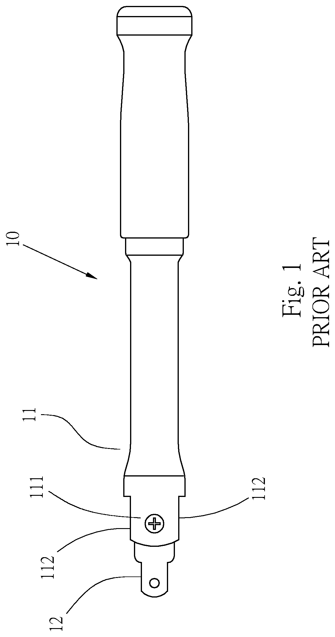
Ear structure of operating rod
- Summary
- Abstract
- Description
- Claims
- Application Information
AI Technical Summary
Benefits of technology
Problems solved by technology
Method used
Image

Examples
Embodiment Construction
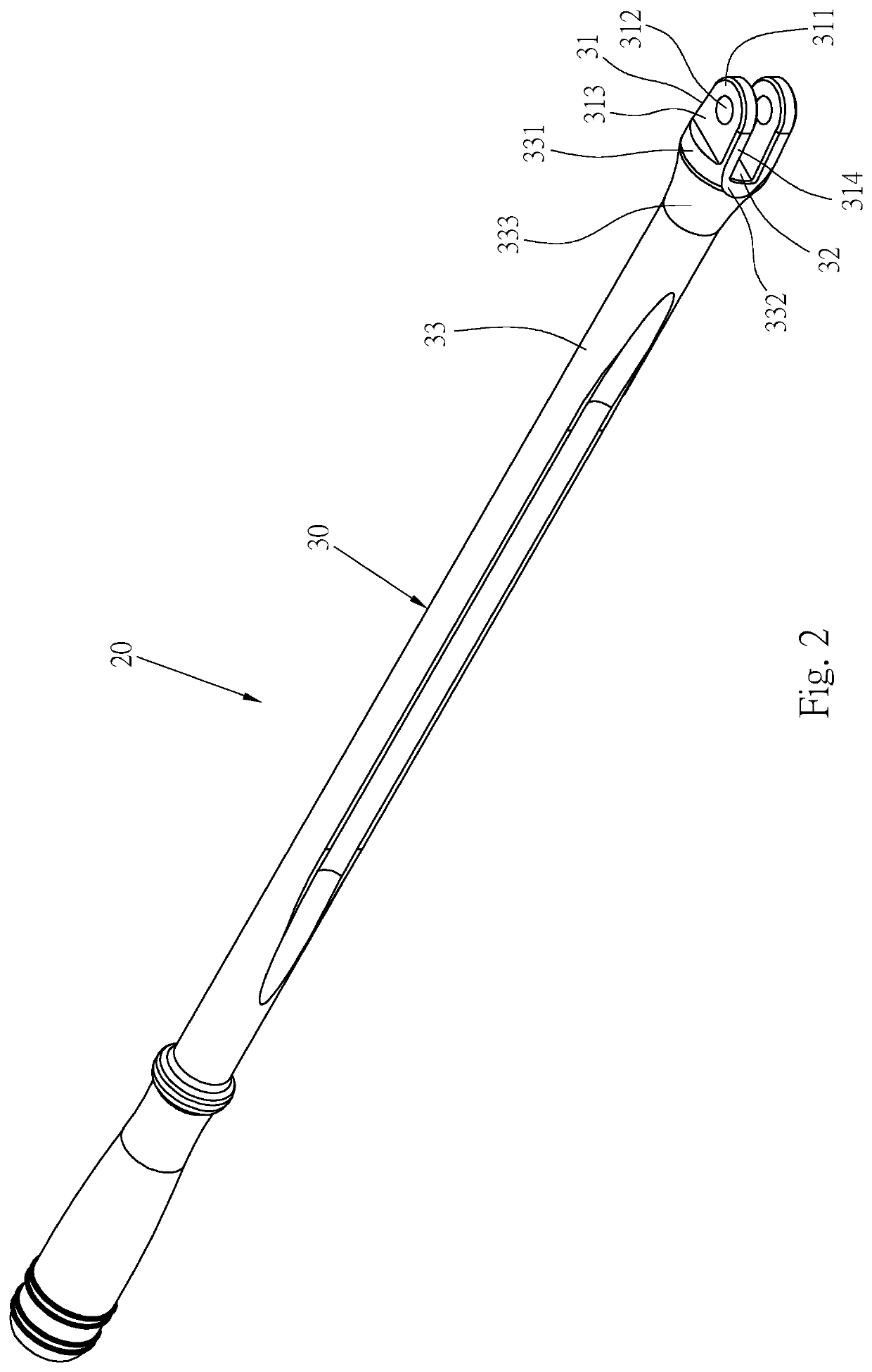
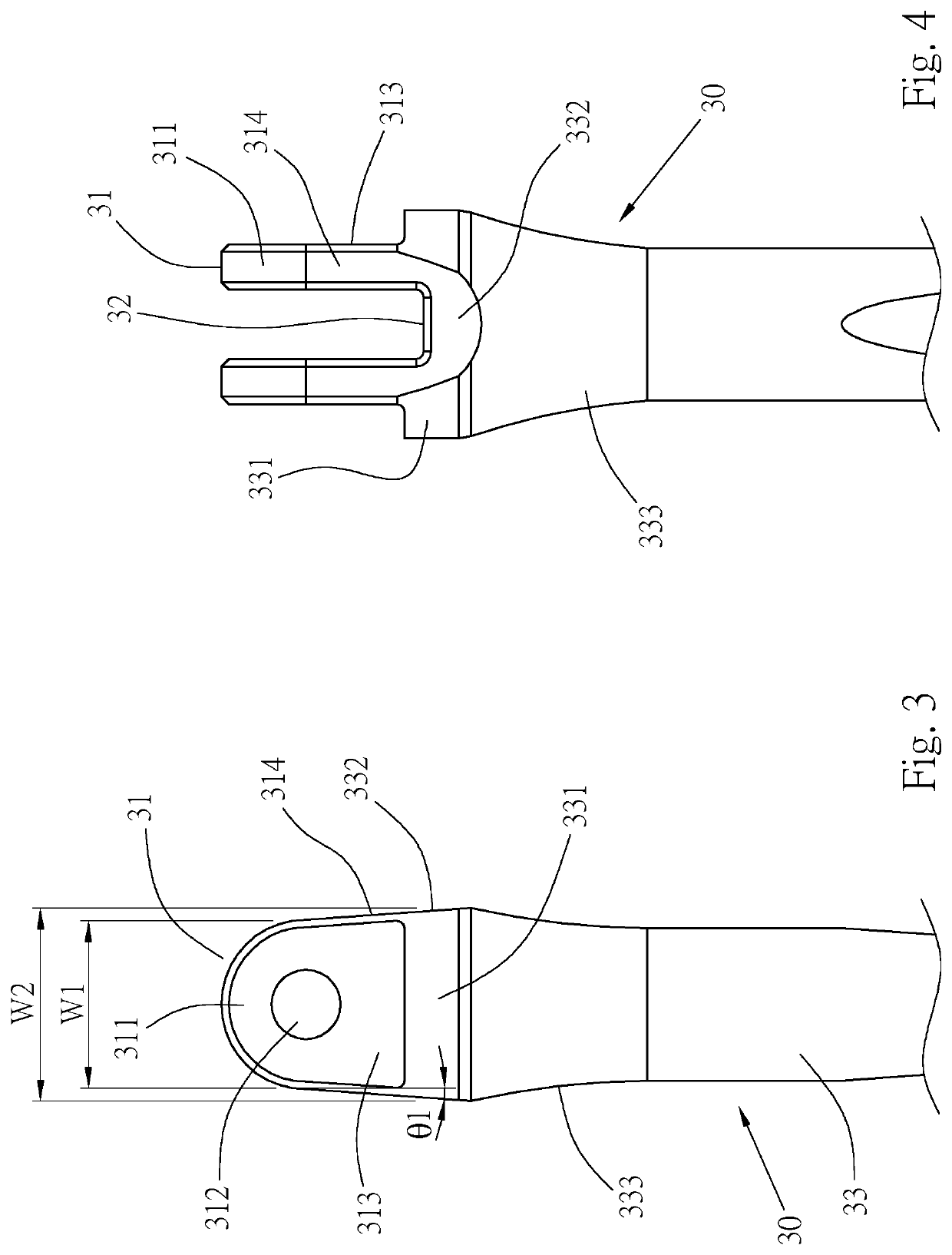
[0019]Please refer to FIGS. 2 to 5, which are a hand tool 20 provided by one preferred embodiment of the invention. The hand tool 20 includes a main rod 30 and a working head 40.
[0020]Please refer to FIGS. 2 to 3, a front end of the main rod 30 is provided with two parallel and spaced ears 31, and a rear end thereof is provided with a shaft 33. A front end of each of the two ears 31 is an assembling end 311 with a largest width of W1, a top edge of each of the two assembling ends 311 is formed as an arcuate surface, and a through hole 312 penetrates through a center of each of the two assembling ends 311. Each of the two ears 31 forms a connecting end 313 at a rear end of each of the two assembling ends 311, and a width W2 of the connecting end 313 is greater than the width W1 of the assembling end 311. A width of each of the two ears 31 gradually increases from the assembling end 311 toward the connecting end 313. In this embodiment, two side edges of the connecting end 313 are res...
PUM
 Abstract
Description
Claims
Application Information