Suction cup holder and method of suctioning and positioning mobile product

a technology of suction cup and mobile product, which is applied in the field of suction cup holder and a mobile product suctioning and positioning method, can solve the problems of troublesome operation, poor controllability, complicated structure of structure, etc., and achieve the effect of reducing the volume of space, and increasing the volume of spa

Inactive Publication Date: 2021-02-18
SHENZHEN ANNAIJIA ELECTRONICS CO LTD
View PDF0 Cites 3 Cited by
  • Summary
  • Abstract
  • Description
  • Claims
  • Application Information

AI Technical Summary

Benefits of technology

[0010]According to one aspect of the present invention, a suction cup holder is provided. The suction cup holder comprises a suction cup and a mounting portion for mounting the suction cup. The suction cup has a disk body and a deformable suction panel disposed on one side of the disk body. The suction cup is moveable relative to the mounting portion. The deformable suction panel is deformable relative to the disk body. When the suction cup is moved from a first position to a second position relative to the mounting portion, the deformable suction panel is linked to be deformed inward to increase the volume of a space between a mobile product and the deformable suction panel to form a negative pressure. When the suction cup is moved from the second position to the first position relative to the mounting portion, the deformable suction panel is linked to be returned outward to reduce the volume of the space between the mobile product and the deformable suction panel.
[0011]According to another aspect of the present invention, a method of suctioning and positioning a mobile product is provided. The method comprises: when the mobile product is placed, a suction cup being moved from a first position to a second position and a deformable suction panel being linked to be deformed inward to increase the volume of a space between the mobile product and the deformable suction panel to form a negative pressure; when the mobile product is taken out, the suction cup being moved from the second position to the first position and the deformable suction panel is linked to be returned outward to reduce the volume of the space between the mobile product and the deformable suction panel.
[0012]Compared with the prior art, the present invention has obvious advantages and beneficial effects. Specifically, it can be known from the above technical solutions that the suction cup is movably disposed relative to the mounting portion, and the deformable suction panel is linked to be deformed inward or returned outward when the suction cup is moved relative to the mounting portion. This method has a simpler mechanical structure, which is beneficial for reducing the cost of the suction cup holder, and can be better promoted and applied to benefit the users. When placing or taking a mobile product (such as a mobile phone, etc.), the suction cup is moved by means of the mobile product's gravity, which is easy to operate, practical, and controllable.

Problems solved by technology

This structure has complicated structure, poor controllability, etc.
The operation is troublesome.
The structure is complicated, the operation is troublesome, and the controllability is not good.

Method used


Image

  • Suction cup holder and method of suctioning and positioning mobile product
  • Suction cup holder and method of suctioning and positioning mobile product
  • Suction cup holder and method of suctioning and positioning mobile product

Examples


Embodiment Construction

[0032]Embodiments of the present invention will now be described, by way of example only, with reference to the accompanying drawings.

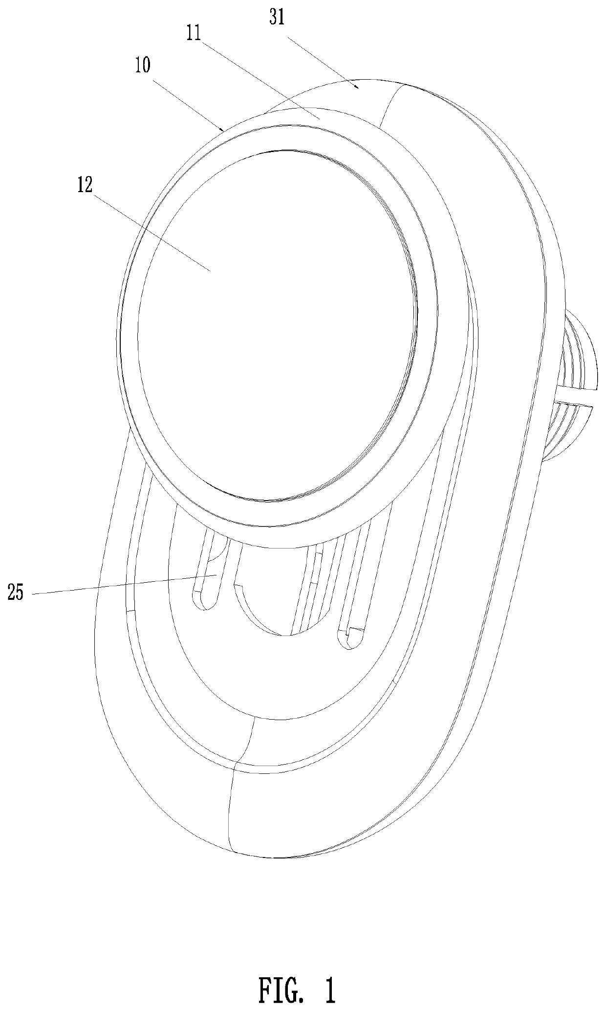
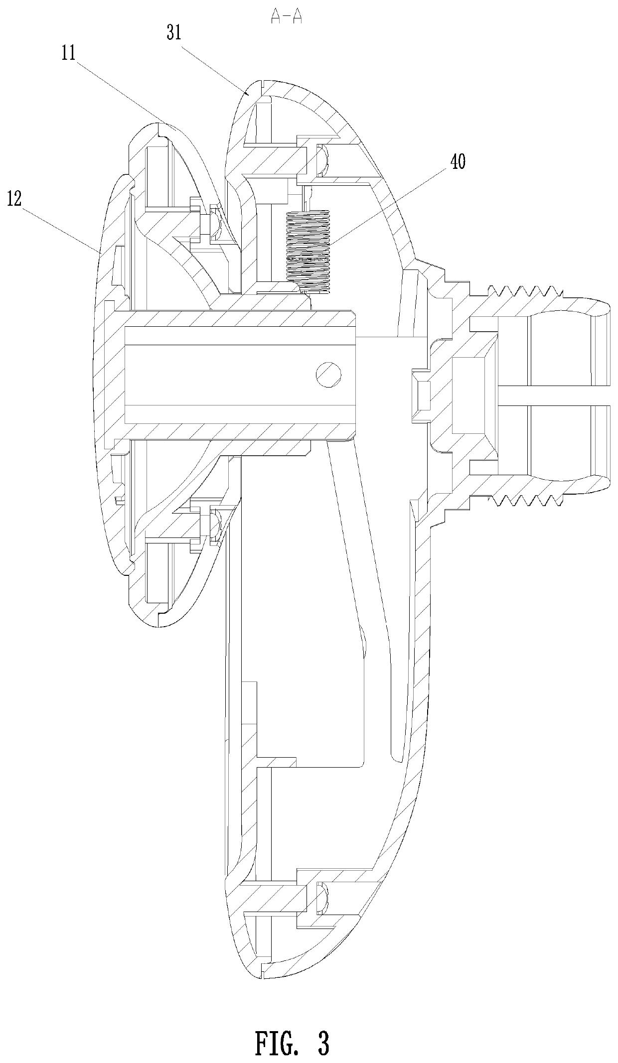
[0033]FIGS. 1 to 22 illustrate the specific structures of various embodiments of the suction cup holder of the present invention. The suction cup holder is used for suctioning and positioning mobile electronic products, such as mobile phones, and it may be used for suctioning other products having a relatively flat and smooth surface to be suctioned.

[0034]The suction cup holder comprises a suction cup 10 and a mounting portion for mounting the suction cup 10. The suction cup 10 has a disk body 11 and a deformable suction panel 12 disposed on one side of the disk body 11. The suction cup 10 is moveable relative to the mounting portion. The deformable suction panel 12 is deformable relative to the disk body 11. When the suction cup 10 is moved from a first position to a second position relative to the mounting portion, the deformable suction panel 12 is...


PUM


Abstract

A suction cup holder and a method of suctioning and positioning a mobile product are disclosed. The suction cup holder includes a suction cup and a mounting portion for mounting the suction cup. The suction cup has a disk body and a deformable suction panel disposed on one side of the disk body. The suction cup is moveable relative to the mounting portion. The deformable suction panel is deformable relative to the disk body. Thus, the deformable suction panel is linked to be deformed and returned by movement of the suction cup. The structure is simple, the controllability is good, and the utility is strong.

Description

BACKGROUND OF THE INVENTION1. Field of the Invention[0001]The present invention relates to a holder, and more particularly to a suction cup holder and a method of suctioning and positioning a mobile product, which is mainly used for suctioning and positioning mobile electronic products such as mobile phones, but not limited thereto.2. Description of the Prior Art[0002]Nowadays, there are three types of suction cup holders on the market.[0003]The first is to control the pressure through an air pump to control the gas in the space between the mobile phone and the holder, so that the mobile phone can be suctioned and positioned to or separated from the holder. This structure has complicated structure, poor controllability, etc.[0004]The second is to control the opening and closing of an air hole. When the mobile phone is placed in the holder, the holder is manually pressed to form a vacuum chamber for suctioning and positioning the mobile phone. When the mobile phone needs to be taken ...

Claims


Application Information

Patent Timeline
Patent Type & Authority Applications(United States)
IPC IPC(8): F16B47/00H04B1/3888
CPCF16B47/00H04B1/3888F16M13/02F16B5/0664F16B2200/83
Inventor YANG, WEIZHAO
Owner SHENZHEN ANNAIJIA ELECTRONICS CO LTD
Why Eureka
Try Eureka