
Actuator device using current-addressed electroactive polymer

a current-addressed, electroactive polymer technology, applied in piezoelectric/electrostrictive devices, device details, device details, etc., can solve the problems of imperfect voltage driven devices, difficult individual actuation, and become expensive to drive each actuator individually. , to achieve the effect of improving the active matrix addressing

Inactive Publication Date: 2021-02-18
KONINKLJIJKE PHILIPS NV
View PDF3 Cites 1 Cited by
  • Summary
  • Abstract
  • Description
  • Claims
  • Application Information

AI Technical Summary

Benefits of technology

This device allows for an actuator to be driven in two directions with current, making it bidirectional. It can switch between states or maintain them. This is useful for current-driven actuators. The device also helps avoid large amounts of charge being transported in the actuators which can cause delays. Boost transistors enable accurate control over charging and discharging currents in two modes - one for implementing actuation level changes and another for sustain function.

Problems solved by technology

For example Voltage driven devices may be imperfect (due to example given leakage) and require a constant current to maintain an achieved state of actuation.
In such cases it quickly becomes expensive to drive each actuator individually with its own driver IC and individual actuation is not easy because of crosstalk.
When a signal is applied to actuate one actuator, the actuators around it also will partially actuate, which is an unwanted effect for many applications.
Hence, with a passive matrix addressing scheme it is not straightforward to individually address each actuator independently of the others.
This approach is however not suitable for driving EAPs in which current control as described herein above is required.

Method used


Image

  • Actuator device using current-addressed electroactive polymer
  • Actuator device using current-addressed electroactive polymer
  • Actuator device using current-addressed electroactive polymer

Examples


Embodiment Construction

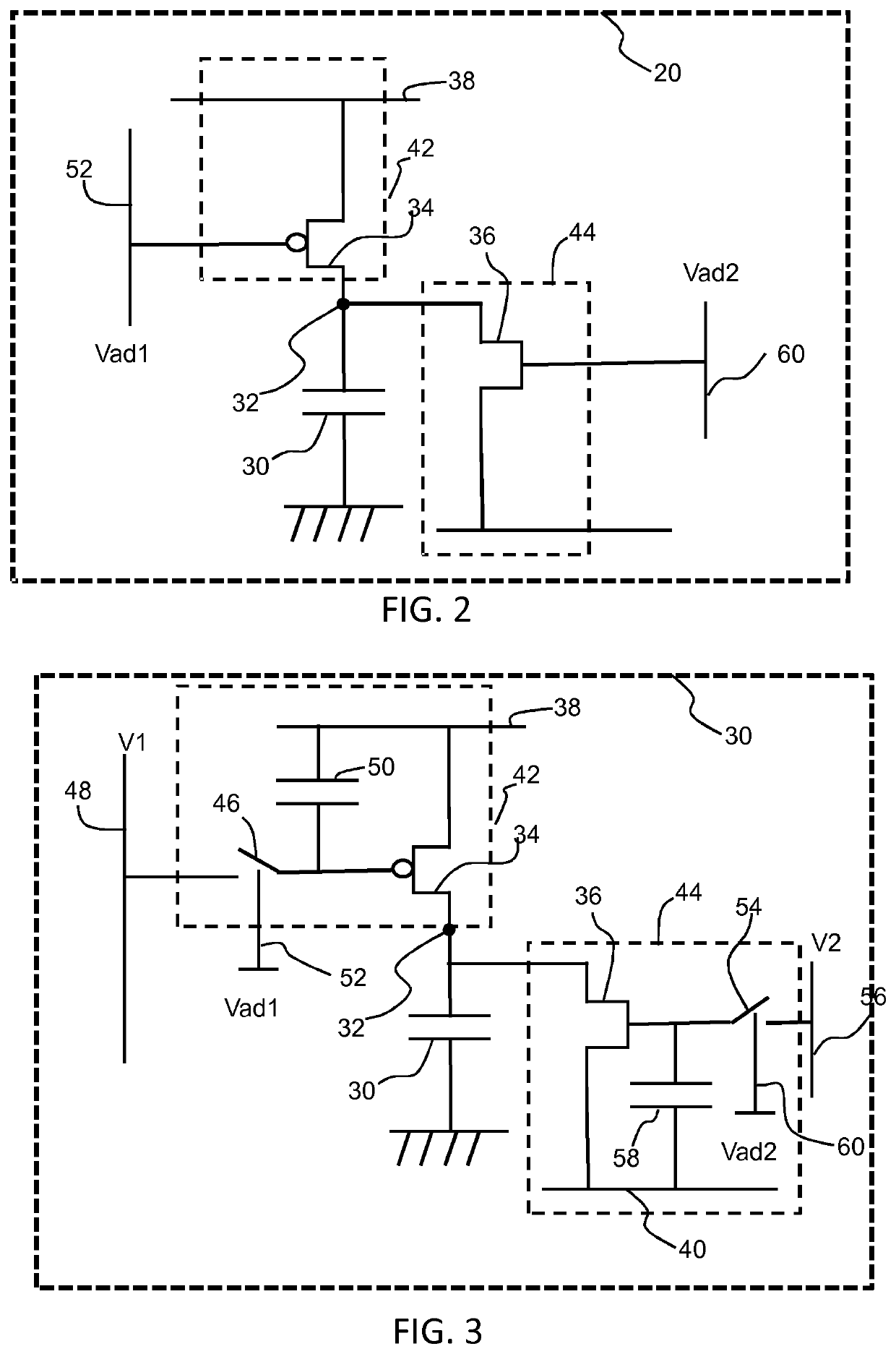
[0080]The invention provides a device with an actuator unit having an electroactive actuator and a drive unit for driving the electroactive actuator with current in two opposite directions to therewith allow or cause bidirectional actuation or bidirectional switching of actuator.

[0081]FIG. 2 shows a first example of an actuator unit 20 as part of a device according to one or more of the claims.

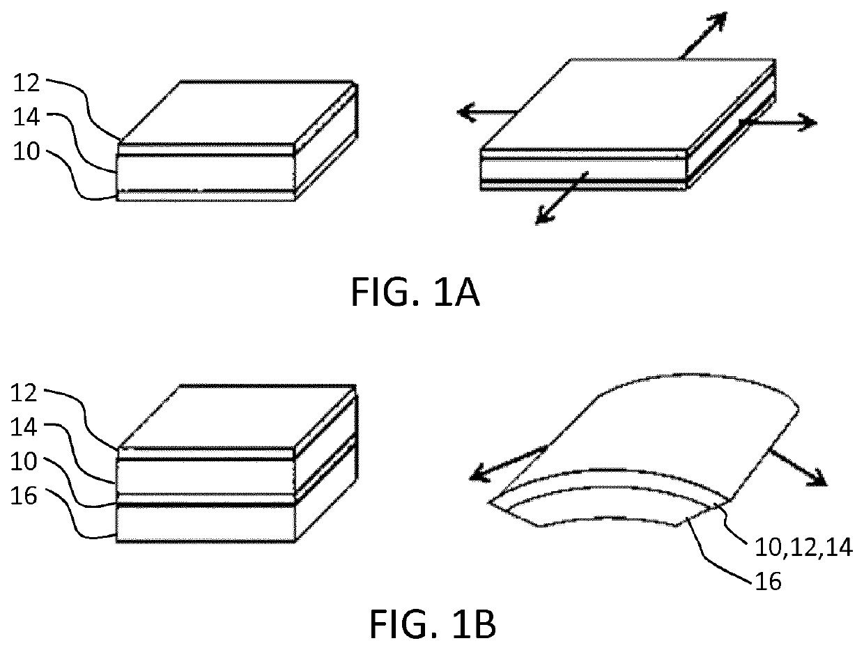
[0082]The actuation unit comprises an electroactive actuator 30 having at least two electrodes for driving the actuator. For example, the actuator may be of the type of FIG. 1A or 1B or, alternatively, of another type of electroactive actuator. One electrode of the actuator 30 is connected to an electrical reference, which in this case is a ground terminal, and the other electrode is connected to a node 32. The node is at the junction between a first transistor 34 and a second transistor 36 which transistors are in series with each other between a first powerline 38 and a second power line 40....


PUM

PropertyMeasurementUnit
currentaaaaaaaaaa
voltageaaaaaaaaaa
electrically responsiveaaaaaaaaaa

Abstract

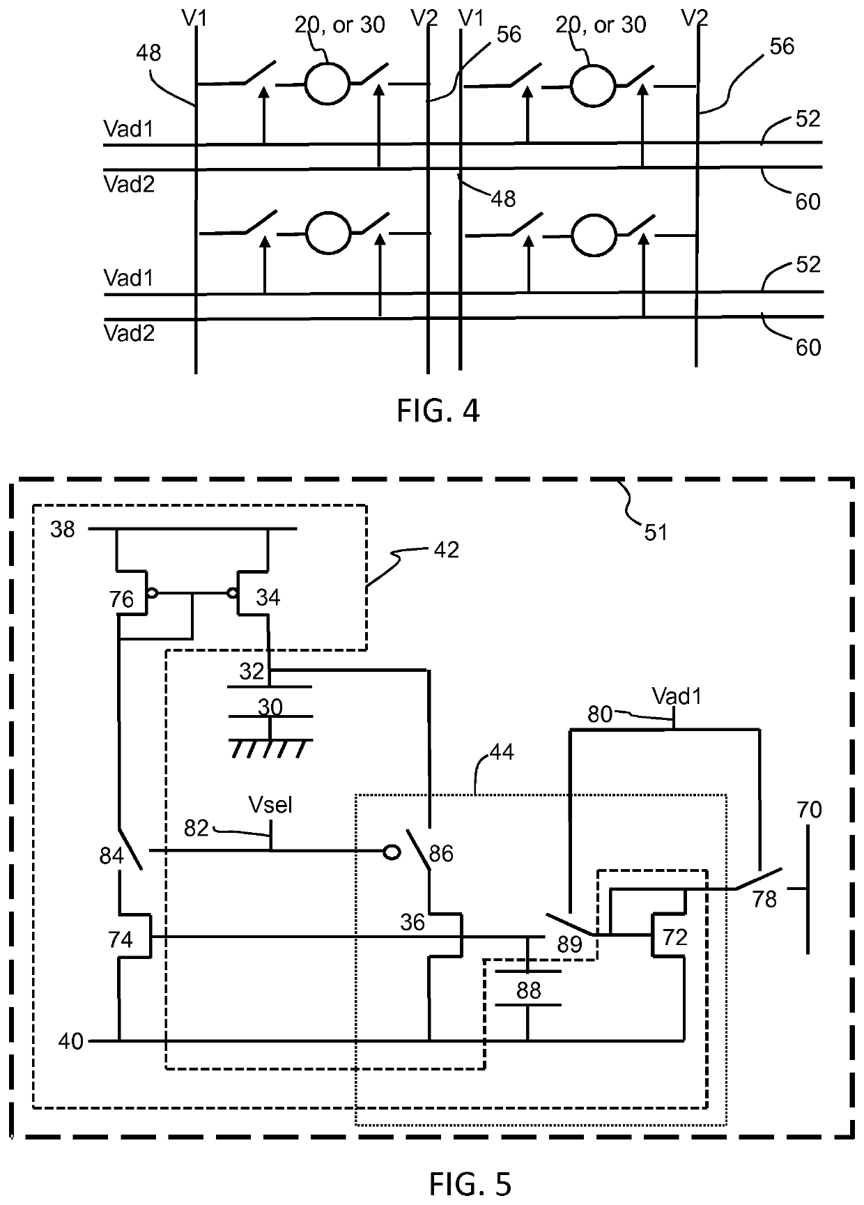
The device as defined by the claims comprises electroactive polymer actuators (30) each of which is addressed by two addressing lines for selecting the electroactive polymer actuator and a current direction drive mode. A first circuit (42) is for driving a controllable current through the electroactive actuator in a first direction and a second circuit (44) is for driving a controllable current through the electroactive actuator in a second direction, opposite to the first direction. This device enables an actuator to be driven with current in two opposite directions so that the actuator may be driven bidirectionally between actuation states.

Description

CROSS-REFERENCE TO RELATED APPLICATIONS[0001]The present application is a U.S. National Phase application under 35 U.S.C. § 371 of International Application No. PCT / EP2019 / 052032, filed on Jan. 29, 2019, which claims the benefit of European Patent Application No. 18156078.0, filed on Feb. 9, 2018. These applications are hereby incorporated by reference herein.FIELD OF THE INVENTION[0002]This invention relates to actuator array devices which make use of electroactive polymers, in particular current-addressed electroactive polymers.BACKGROUND OF THE INVENTION[0003]Electroactive polymers (EAP) are an emerging class of materials within the field of electrically responsive materials. EAPs can work as sensors or actuators and can easily be manufactured into various shapes allowing easy integration into a large variety of systems.[0004]Materials have been developed with characteristics such as actuation stress and strain which have improved significantly over the last ten years. Technology...

Claims


Application Information

Patent Timeline
Patent Type & Authority Applications(United States)
IPC IPC(8): H01L41/04H10N30/80H10N30/20H10N30/857
CPCH01L41/042H01L41/193H10N30/802H10N30/857
Inventor JOHNSON, MARK THOMASFISH, DAVID ANDREW
Owner KONINKLJIJKE PHILIPS NV
Learn More