

Developing roller, developing device, image forming apparatus, and developing roller manufacturing method
a technology of developing device and developing roller, which is applied in the direction of electrographic process apparatus, instruments, optics, etc., can solve the problems of ineffective electrical charging of excrement portions, inability to effectively electrically charge, and inability to produce film, so as to increase the amount of toner
- Summary
- Abstract
- Description
- Claims
- Application Information
AI Technical Summary
Benefits of technology
Problems solved by technology
Method used
Image

Examples
Embodiment Construction
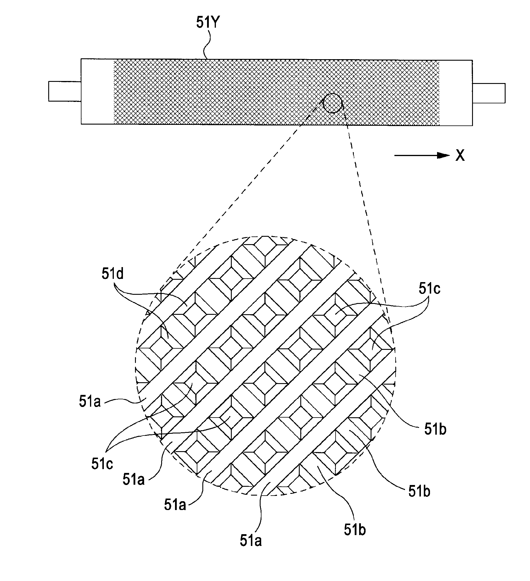
of the rolling process for forming the intersecting inclined grooves having different groove depths in the developing roller.
[0029]FIGS. 8A and 8B are diagrams showing Example 2 of the rolling process for forming the intersecting inclined grooves having different groove depths in the developing roller.
DESCRIPTION OF EXEMPLARY EMBODIMENTS
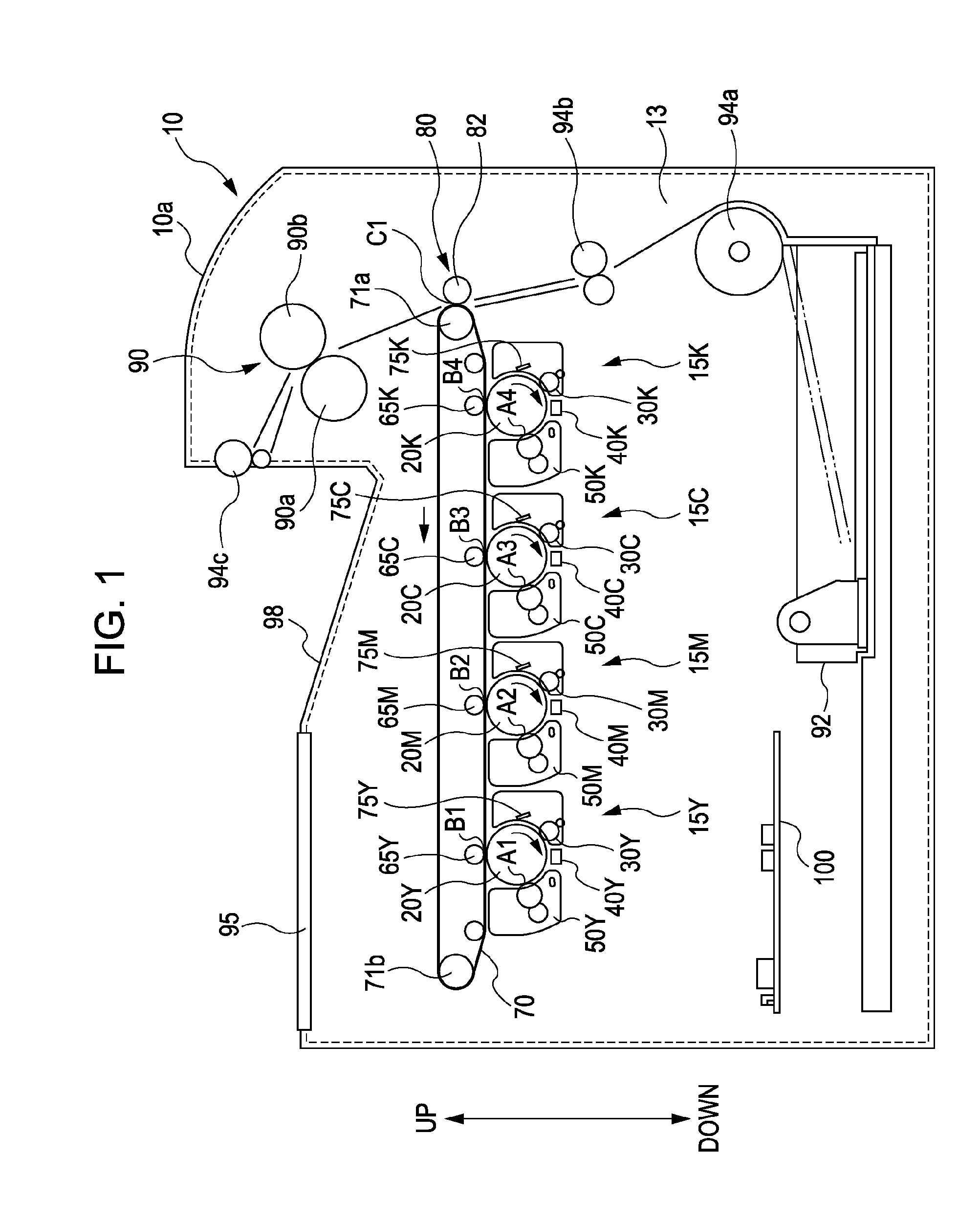
[0030]Hereinafter, embodiments of the invention will be explained based on the drawings. FIG. 1 is a diagram schematically illustrating an image forming apparatus according to an embodiment of the invention.
[0031]As shown in FIG. 1, the image forming apparatus 10 includes four image forming stations 15Y, 15M, 15C, and 15K; an intermediate transferring belt 70; a secondary transferring unit 80; a fixing unit 90; a display unit 95 which is configured of a liquid crystal panel constituting a means of messaging to a user; and a control unit 100 which controls these units and the like and manages the operation of the image forming apparatus. The image for...
PUM
 Abstract
Description
Claims
Application Information