
Dust Boot Tool

Active Publication Date: 2021-02-25
CHUAN JIING ENTERPRISE CO LTD
View PDF0 Cites 0 Cited by
  • Summary
  • Abstract
  • Description
  • Claims
  • Application Information

AI Technical Summary

Benefits of technology

The present invention provides a dust boot tool that automatically stops expanding when it reaches its proper extent. The tool includes a shell, piston, valve, and stretchable rods. The piston is moved by pressurized air and has a conical internal face. The valve has a portion that moves into the conical internal face. The stretchable rods have a stretchable end for contact with the dust boot, an abutment end in contact with the conical internal face of the piston, and a pivotal portion. The technical effects of this invention include automatic stopping of expansion, improved control and efficiency of the dust boot tool, and simplified usage.

Problems solved by technology

However, the user could easily over-expand and hence damage the dust boot.
However, it is difficult for the user to hear the sound in a noisy environment such as a garage.

Method used


Image

  • Dust Boot Tool
  • Dust Boot Tool
  • Dust Boot Tool

Examples


first embodiment

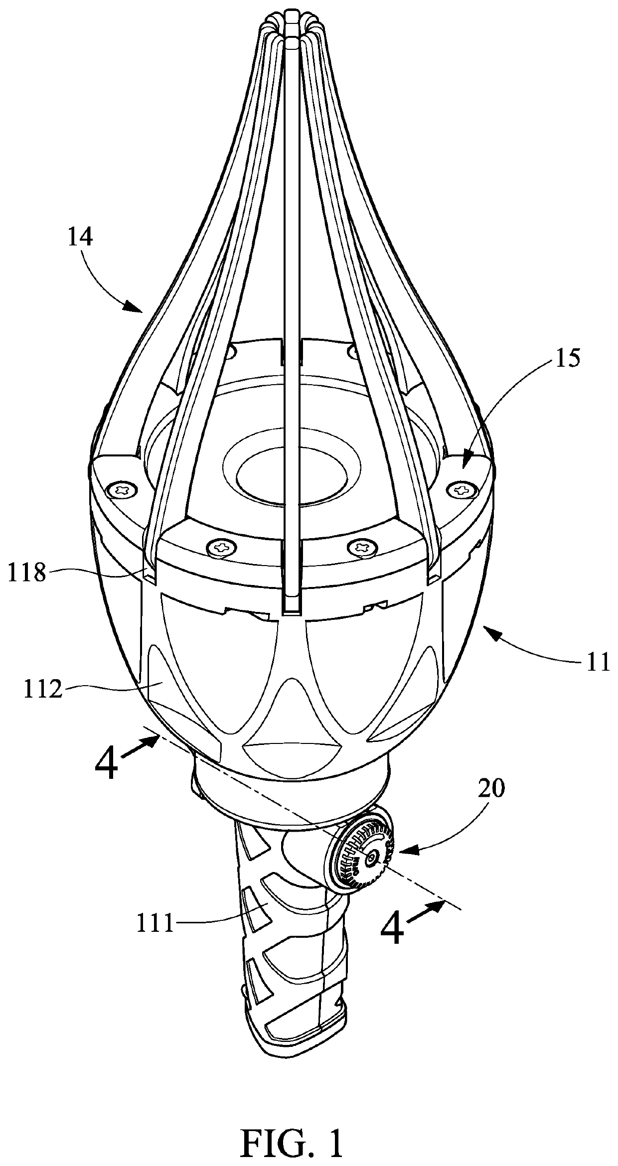
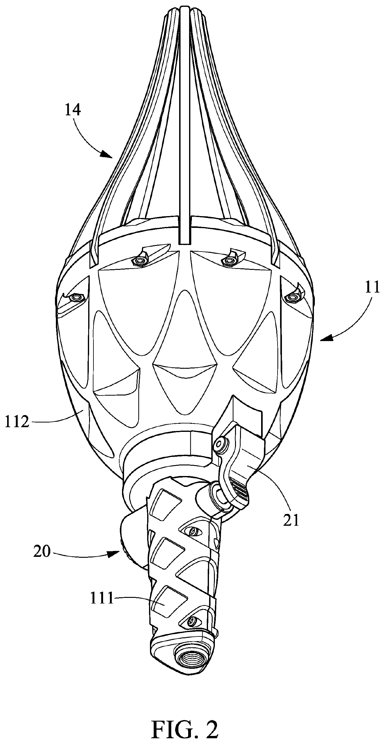
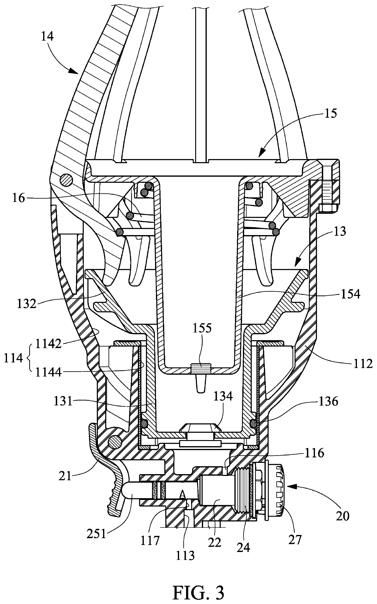
[0030]Referring to FIGS. 1 through 4, a dust boot tool includes a shell 11, a seal assembly 12, a piston 13, stretchable rods 14, a cap 15, an elastic element 16 and an air controller 20 according to the present invention.

[0031]Referring to FIGS. 1 to 7, the shell 11 includes a handle 111, a bowl 112, an inlet channel 113, a chamber 114, a regulator channel 115, two regulator apertures 116 and 117, slits 118 and recesses 119.

[0032]The handle 111 and the bowl 112 are formed at two opposite ends of the shell 11.

[0033]Referring to FIGS. 3 through 6, the inlet channel 113 is made in the handle 111 and the chamber 114 is made in the bowl 112. The inlet channel 113 is in communication with the chamber 114. The inlet channel 113 and the chamber 114 are both in communication with the exterior of the shell 11. The chamber 114 includes a wide section 1142 in the vicinity of a front end and a narrow section 1144 in the vicinity of a rear end. A pump (not shown) can be used to pump pressurized ...

second embodiment

[0049]Referring to FIG. 12, the pushing element 155′ is made in one piece with the cup-shaped portion 154 according to the present invention.

[0050]Referring to FIGS. 3, 5 and 9, the elastic element 16 is preferably a helical spring located around the cup-shaped portion 154. The elastic element 16 includes an upper end in contact with the disc-shaped portion 151 and a lower end in contact with the stretchable rods 14 to open the stretchable ends 141 of the stretchable rods 14.

[0051]Referring to FIGS. 1 through 7, 13 and 14, the air controller 20 extends throughout the regulator channel 115 to adjust the flow rate of the pressurized air into the chamber 114 via the inlet channel 113 or completely shut down the pressurized air. The air controller 20 includes a trigger 21, a sleeve 22, a collar 23, a cover 24, a valve rod 25, an elastic element 26 and a knob 27.

[0052]The trigger 21 is pivotally connected to an external portion of the bowl 114. The trigger 21 is aligned with the narrow s...


PUM


Abstract

A dust boot tool includes a shell, a piston, a valve and stretchable rods. The shell includes a chamber in communication with an inlet channel. Pressurized air enters the chamber via the inlet channel. The piston is movable in the chamber by the pressurized air, and includes a first section, a second section opposite to the first section, a vent in the first section in the vicinity of the inlet channel, and a conical internal face extending on the second section. The valve includes a portion movably inserted in the vent. Each of the stretchable rods includes a stretchable end for contact with a dust boot, an abutment end in contact with the conical internal face of the second section of the piston, and a pivotal portion formed between the stretchable end and the abutment end and pivotally connected to the shell.

Description

BACKGROUND OF INVENTION1. Field of Invention[0001]The present invention relates to a tool for vehicles and, more particularly, to a tool for dust boots of drive shafts of vehicles.2. Related Prior Art[0002]An end of a drive shaft of a vehicle is inserted in and hence protected by a dust boot. A specialized tool is needed to locate the dust boot around the end of the drive shaft or remove the dust boot from the end of the drive shaft.[0003]For example, Taiwanese Patent No. I330580 discloses a tool that uses pressurized air to push a piston in a cylinder. The piston pushes and hence causes stretchable rods to expand the dust boot. A user has to depend on his or her own discretion to control the extent to which he or she expands the dust boot with the tool. However, the user could easily over-expand and hence damage the dust boot.[0004]Taiwanese Patent No. I554357 discloses a tool to solve the above-mentioned problems. This tool includes an indicating device located on the piston. When...

Claims


Application Information

Patent Timeline
IPC IPC(8): B25B27/00
CPCB25B27/0035F16D3/84
Inventor TSENG, TIEN-TSAI
Owner CHUAN JIING ENTERPRISE CO LTD
Learn More