
Optics for vehicle occupant monitoring systems

a vehicle and monitoring system technology, applied in the field of environmental mapping and surveying, can solve the problems of large data traffic and processing resources, and achieve the effect of reducing the amount of light that exits through the input surfa

Pending Publication Date: 2021-02-25
NEONODE
View PDF3 Cites 1 Cited by
  • Summary
  • Abstract
  • Description
  • Claims
  • Application Information

AI Technical Summary

Benefits of technology

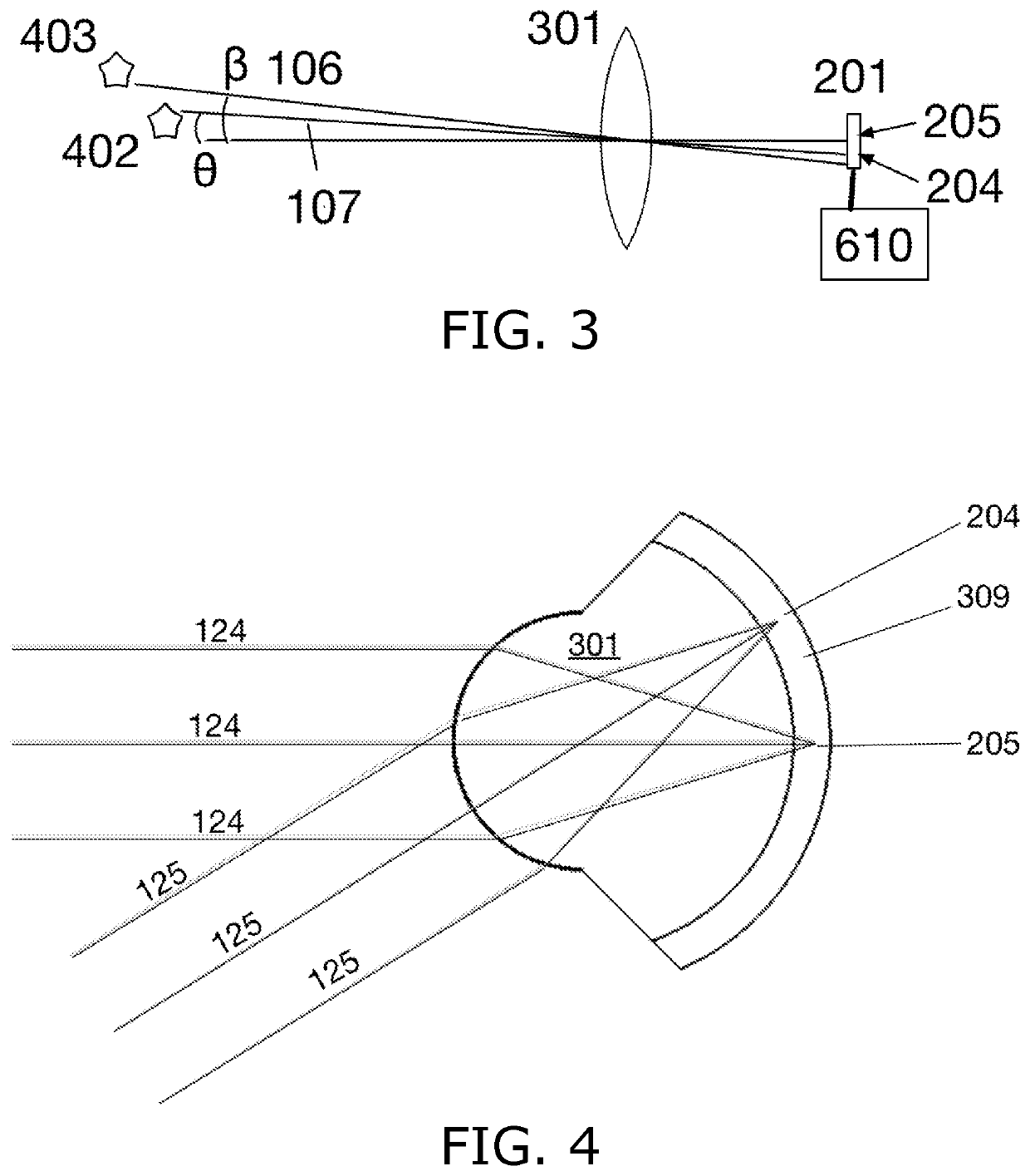
The invention features a reflective objective that causes some of the light to bounce back and exit through the same hole that it enters. This is done through a convex surface that refracts the light in a way that minimizes the amount of light that can be seen through the surface. This leads to a more precise and controllable beam of light.

Problems solved by technology

Prior art camera-based 3D sensors bend image data for further analysis and thus involve large amounts of data traffic and processing resources.

Method used


Image

  • Optics for vehicle occupant monitoring systems
  • Optics for vehicle occupant monitoring systems
  • Optics for vehicle occupant monitoring systems

Examples


second embodiment

[0092]In a second embodiment, sensor 506 provides time of flight detection and is therefore operable to determine both polar angle and radial distance of a reflective object.

third embodiment

[0093]In a third embodiment, multiple sensors are placed at different locations such that their detection zones 603 partially overlap, whereby objects detected by more than one sensor are triangulated.

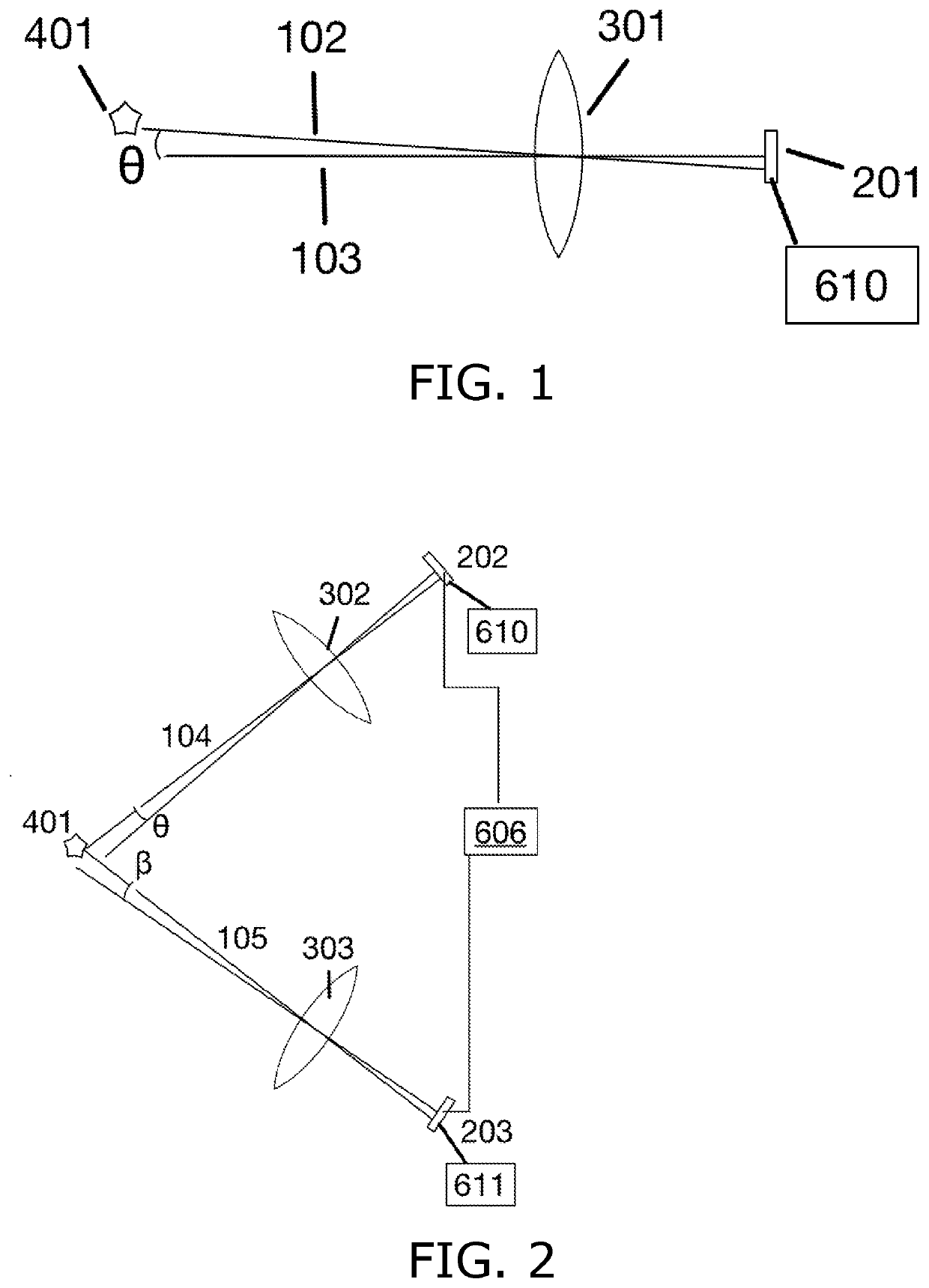
[0094]As discussed hereinabove, an illuminator, inter alia one or more LEDs, VCSELs or lasers, is provided for each polar coordinate sensor and spherical coordinate sensor to create detected reflections. Reference is made to FIGS. 26 and 27, which are illustrations of sensor illumination schemes, in accordance with embodiments of the present invention. FIG. 26 shows an illuminator configuration in which different illuminators illuminate 140-145 different areas of a display or detection zone for a directional sensor, and FIG. 27 shows an illuminator configuration for a sensor at the center of a detection zone. The illumination schemes of FIGS. 26 and 27 enable illuminating only those parts of the detection zone in which the object is likely to be located. For example, when a moving obje...


PUM


Abstract

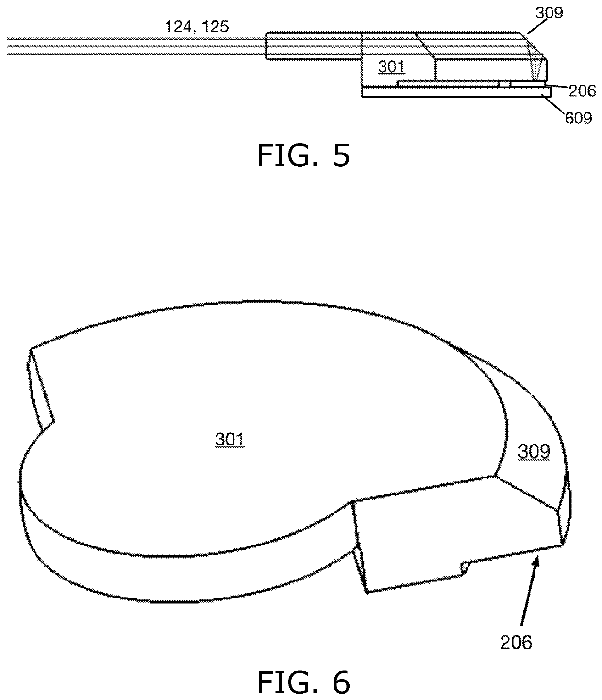
A focusing optical part, including a plastic body, suitable for being delivered on a tape and reel and mounted on a PCB by an automated mounting machine, the plastic body including a concave mirror including a center aperture input surface through which light enters the plastic body, a convex mirror opposite the center aperture, wherein the concave mirror and the convex mirror form a reflective objective that reflects and focuses the light inside the plastic body, and an exit surface surrounding the convex mirror, through which focused light exits the plastic body.

Description

CROSS-REFERENCE TO RELATED APPLICATIONS[0001]This application claims benefit under 35 U.S.C. § 371 of PCT Application No. PCT / US2019 / 014667 entitled POLAR COORDINATE SENSOR, filed on Jan. 23, 2019 by inventors Alexander Jubner, Lars Bertil Sparf, Robert Sven Pettersson and Stefan Johannes Holmgren. PCT Application No. PCT / US2019 / 014667 claims priority of U.S. Provisional Patent Application No. 62 / 621,644, filed on Jan. 25, 2018 by inventors Alexander Jubner, Lars Bertil Sparf, Robert Sven Pettersson and Stefan Johannes Holmgren.FIELD OF THE INVENTION[0002]The field of the present invention is environmental mapping and surveying by identifying the position and contour of objects on a plane or in space using light reflections. Applications include touch screen sensors, gesture sensors, 3D scanning to create three-dimensional models, object detection in collision avoidance systems for vehicles and drones, and vehicle occupant monitoring.BACKGROUND OF THE INVENTION[0003]Prior art reflec...

Claims


Application Information

Patent Timeline
Patent Type & Authority Applications(United States)
IPC IPC(8): G06K9/46H04N5/225G06K9/20G06K9/00G02B17/06G02B27/00G01S17/42G01S7/481B60R21/015B60R21/013
CPCG06K9/4661B60R21/01538H04N5/2254G06K9/2054G06K9/00845G06K9/00838G06K9/00805G06K9/2027G02B17/0631G02B27/0093G01S17/42G01S7/4816B60R21/01552B60R21/013H04N5/2253G02B13/0065G02B2003/0093G02B19/0076G01B11/26G01S17/88G01S17/48G06F3/0421G06F3/017G06F3/0304G06F3/038G01B11/026B60K35/28B60K2360/179B60K2360/48G02B17/006G06V20/58G06V20/593G06V20/597H04N23/54H04N23/55
Inventor JUBNER, BJÖRN ALEXANDERSPARF, LARS BERTILPETTERSSON, ROBERT SVENJANSSON, HANS ANDERS
Owner NEONODE
Learn More