
Athermal apochromatic telecentric F-theta lens with low F-number

a technology of apochromatic telecentric and lens, applied in the field of optical lenses, can solve the problems of 362 lenses that are not suitable for surveillance and reconnaissance applications, cannot be used in applications requiring a wide spectrum, and are only suitable for laser systems applications, so as to minimize the amount of light lost and light incident

Active Publication Date: 2013-06-11
BAE SYST INFORMATION & ELECTRONICS SYST INTERGRATION INC
View PDF11 Cites 5 Cited by
  • Summary
  • Abstract
  • Description
  • Claims
  • Application Information

AI Technical Summary

Benefits of technology

This patent describes a camera sensor that can be used with a specific type of camera sensor. The sensor has a special lens that focuses light onto the camera sensor's pixels, minimizing the amount of light lost or incident on nearby pixels. This results in a higher resolution image. The lens has a specific diameter and is compatible with a specific camera sensor. The technical effect is a more efficient and accurate camera sensor that can produce higher quality images.

Problems solved by technology

However, the '362 lens would not be suitable for surveillance and reconnaissance applications, since it transmits a very limited amount of light because of its high F# and it has a low resolution.
In addition, the '362 lens is suitable only for monochromatic applications, and cannot be used for applications requiring a wide spectrum.
For all of these reasons, the '383 lens is only suitable for laser systems applications, and not for surveillance and reconnaissance.
In addition, the '280 lens is too large to be used for reconnaissance and surveillance applications.
This lens is not apochromatic and its F# is very large, so it cannot be used in low F# reconnaissance and surveillance systems.
The characterization of optical glass through refractive index and Abbe number alone is not sufficient for high quality optical systems.

Method used


Image

  • Athermal apochromatic telecentric F-theta lens with low F-number
  • Athermal apochromatic telecentric F-theta lens with low F-number
  • Athermal apochromatic telecentric F-theta lens with low F-number

Examples


first embodiment

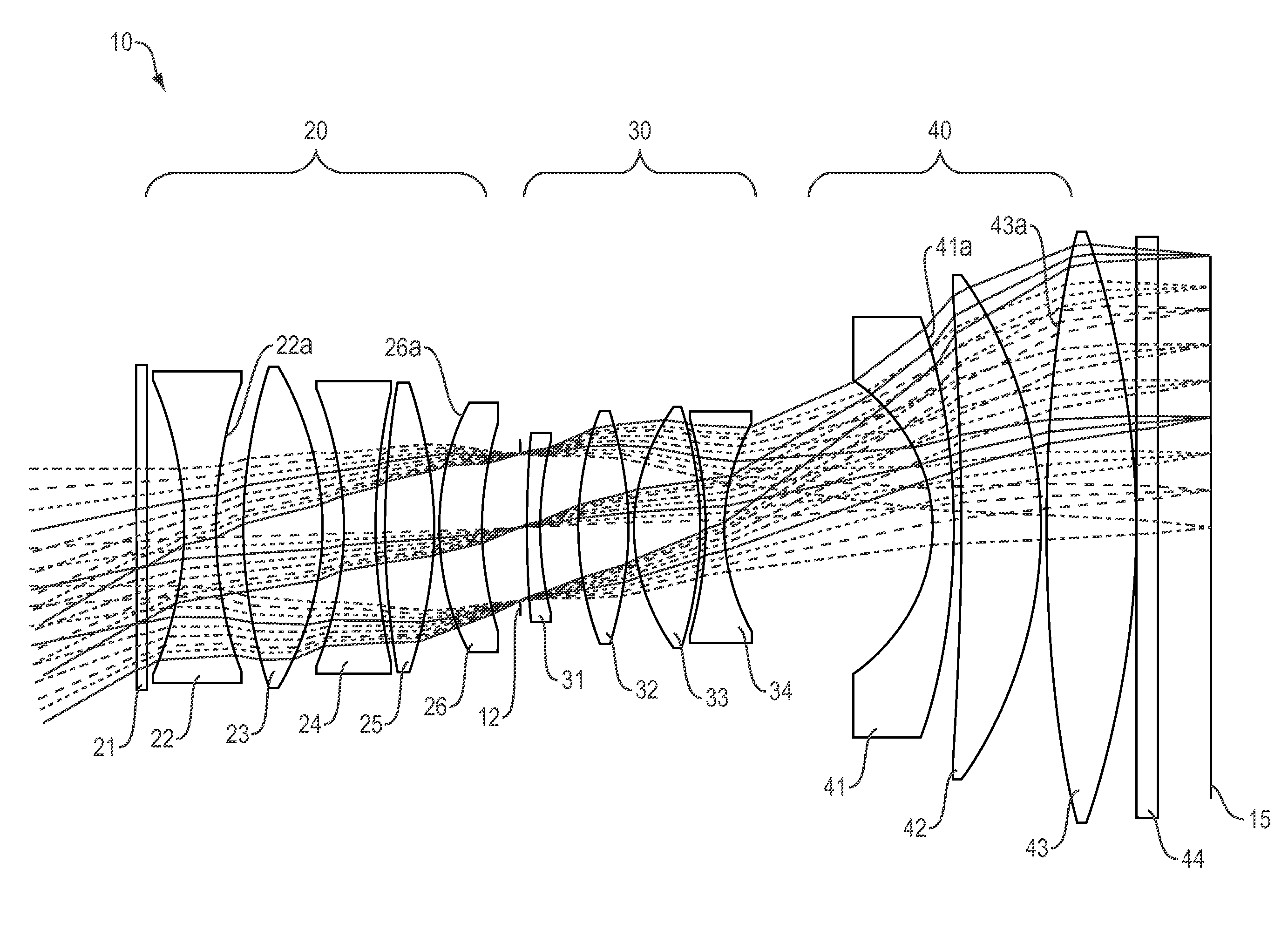
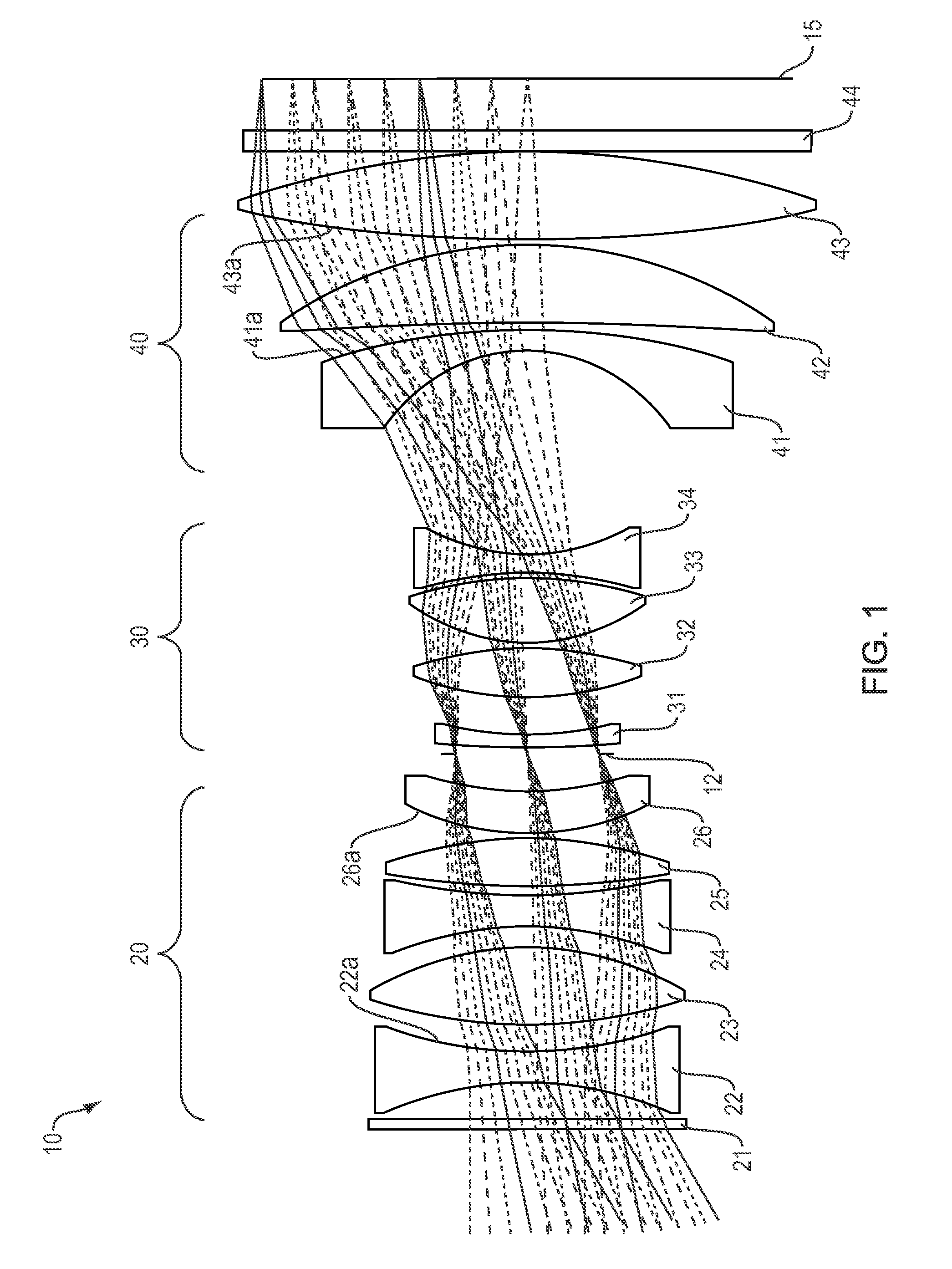
[0104]FIG. 1 is a cross section of the F-theta athermal lens 10 of the present invention. The lens includes a front window 21, a first optical group 20, a second optical group 30, a third optical group 40, and a back window 44 in order from the object to the image plane. An aperture stop 12 is located between the first and the second optical groups. An image of a target is formed on a focal plane array 60. In embodiments, the focal plane array incorporates CMOS with micro lenses, 2×2 Bayer filter geometry, and 1.8 Giga pixels. In other embodiments the image surface 60 incorporates CCD or a direct viewing screen.

[0105]The first optical group 20 has an overall positive optical power and is configured to receive light from the remote object and to direct the converged light onto the second optical group 30. The first optical group 20 includes five optical elements 22, 23, 24, 25 and 26, having, in order from the object to the image plane, a negative optical power, a positive optical po...

second embodiment

[0115]FIG. 8 is a cross sectional illustration of the F-theta athermal lens 100 of the present invention. The lens includes a front window 210, a first optical group 200, a second optical group 300, a third optical group 400 and a back window 440 in order from the object to the image plane 150. The aperture stop 110 is located between the first 200 and the third optical groups. An image of the target is formed on a focal plane array 150. In embodiments, the focal plane array 150 incorporates CMOS with micro lenses, 2×2 Bayer filter geometry, and 1.8 Giga pixels. In other embodiments, the image surface 150 may include CCD elements or a direct viewing screen.

[0116]In the embodiment of FIG. 8, the first optical group 200 has an overall negative optical power and is configured to receive light from a remote object and to direct the diverged light onto the second optical group 300. The first optical group 200 includes five optical elements 220, 230, 240, 250 and 260, having, in order fro...

third embodiment

[0124]FIG. 15 is a cross-sectional illustration of the F-theta athermal lens 1000 of the present invention. The lens 1000 includes a front window 2100, a first optical group 2000, a second optical group 3000, a third optical group 4000 and a back window 4400 in the stated order from the object to the image plane. The aperture stop 1100 is located between the first 2000 and second 3000 optical groups. An image of a remote object is formed on a focal plane array 1500. In embodiments, the focal plane array 1500 incorporates CMOS with micro lenses, 2×2 Bayer filter geometry, and 1.8 Giga pixels. In other embodiments, the image surface 1500 may incorporate CCD devices or a direct viewing screen.

[0125]The first optical group 2000 has an overall negative optical power and is configured to receive light from the remote object and to direct the diverged light onto the second optical group 3000. The first optical group 2000 includes three optical elements 2200, 2300 and 2400, having, in order...


PUM


Abstract

A compact F-theta lens suitable for precise mapping and aerial photography has an F# of not more than 4.5 and a full field of view of 60° (high quality field over) 53°. The lens is near-telecentric to less than 6°, apochromatic from 450 nm to 650 nm, and athermal from −15° C. to +40° C. Embodiments have a focal plane diameter of 104 mm and are compatible for use with a CMOS 1.8 gigapixel multiple FPA. In some embodiments the focal length is 101 mm and the back working distance is more than 10 mm. In embodiments the lens includes three groups of optical elements, with an aperture located between the first and second groups. In some of these embodiments, the first group has at least three elements, while the second and third groups have four and three elements respectively, and the diameter of the first two groups, including housing, is less than 65 mm.

Description

FIELD OF THE INVENTION[0001]The invention relates to optical lenses, and more particularly to F-theta lenses.BACKGROUND OF THE INVENTION[0002]Off axis light beam refraction through a focusing lens system will produce distorted images in a curved plane as opposed to a more desirable flat surface. A flat field scanning lens is a specialized lens system in which the focal plane is a flat surface.[0003]For a typical flat field lens, in the absence of distortion, the beam of light enters the lens at an angle θ compared with the axis of the lens, the position of the spot focused by the lens will be dependent on the product of the focal length (F) of the lens and the tangent of the angle (θ). However, when the lens is designed with built-in barrel distortion, the position of the focused spot can then be made dependent on the product of F and θ, thereby simplifying positioning and image correction algorithms. Lenses designed in this way are called “F-theta” lenses. F-theta lenses are widely...

Claims


Application Information

Patent Timeline
Patent Type & Authority Patents(United States)
IPC IPC(8): G02B3/00G02B26/10
CPCG02B9/12G02B13/18G02B13/22G02B13/0005
Inventor OSKOTSKY, MARK LRUSSO, JR., MICHAEL J
Owner BAE SYST INFORMATION & ELECTRONICS SYST INTERGRATION INC
Learn More