
Lectronic device, connector, and electromagnetic device thereof

a technology of electromagnetic devices and connectors, applied in the direction of coupling device connections, transformers/react mounting/support/suspension, printed circuit non-printed electric components association, etc., can solve problems affecting use, and achieve the effect of more stable connection between the connector assembly and the electromagnetic devi

Pending Publication Date: 2021-02-25
SHENNAN CIRCUITS
View PDF2 Cites 0 Cited by
  • Summary
  • Abstract
  • Description
  • Claims
  • Application Information

AI Technical Summary

Benefits of technology

The invention provides an electromagnetic device with a stable connection between the adapter plate and the connector assembly, which ensures a reliable connection between the electromagnetic device and other components. The insertion slot on the first side of the electromagnetic device ensures uniform force distribution, while the fixed connection between the connector assembly and the electromagnetic device further strengthens the connection.

Problems solved by technology

However, the connector assembly is connected to the surface of the electromagnetic device by means of welding, the connection is unstable, and is prone to cause failure of the connection between the connector assembly and the electromagnetic device, thereby affecting use.

Method used


Image

  • Lectronic device, connector, and electromagnetic device thereof
  • Lectronic device, connector, and electromagnetic device thereof
  • Lectronic device, connector, and electromagnetic device thereof

Examples


Embodiment Construction

[0021]Technical solutions of embodiments of the present disclosure will be clearly and completely described below. Obviously, the described embodiments are merely some embodiments, but not all embodiments of the present disclosure. Based on the embodiments of the present disclosure, all of the other embodiments obtained by one of ordinary skill in the art without making any creative work belong to the protection scope of the present disclosure.

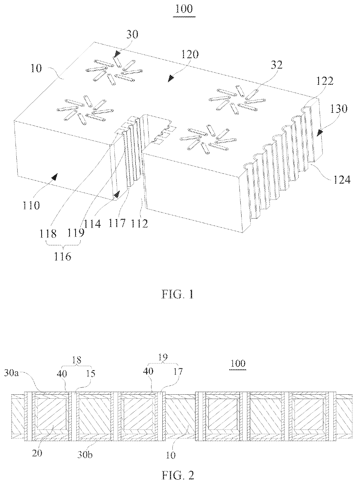
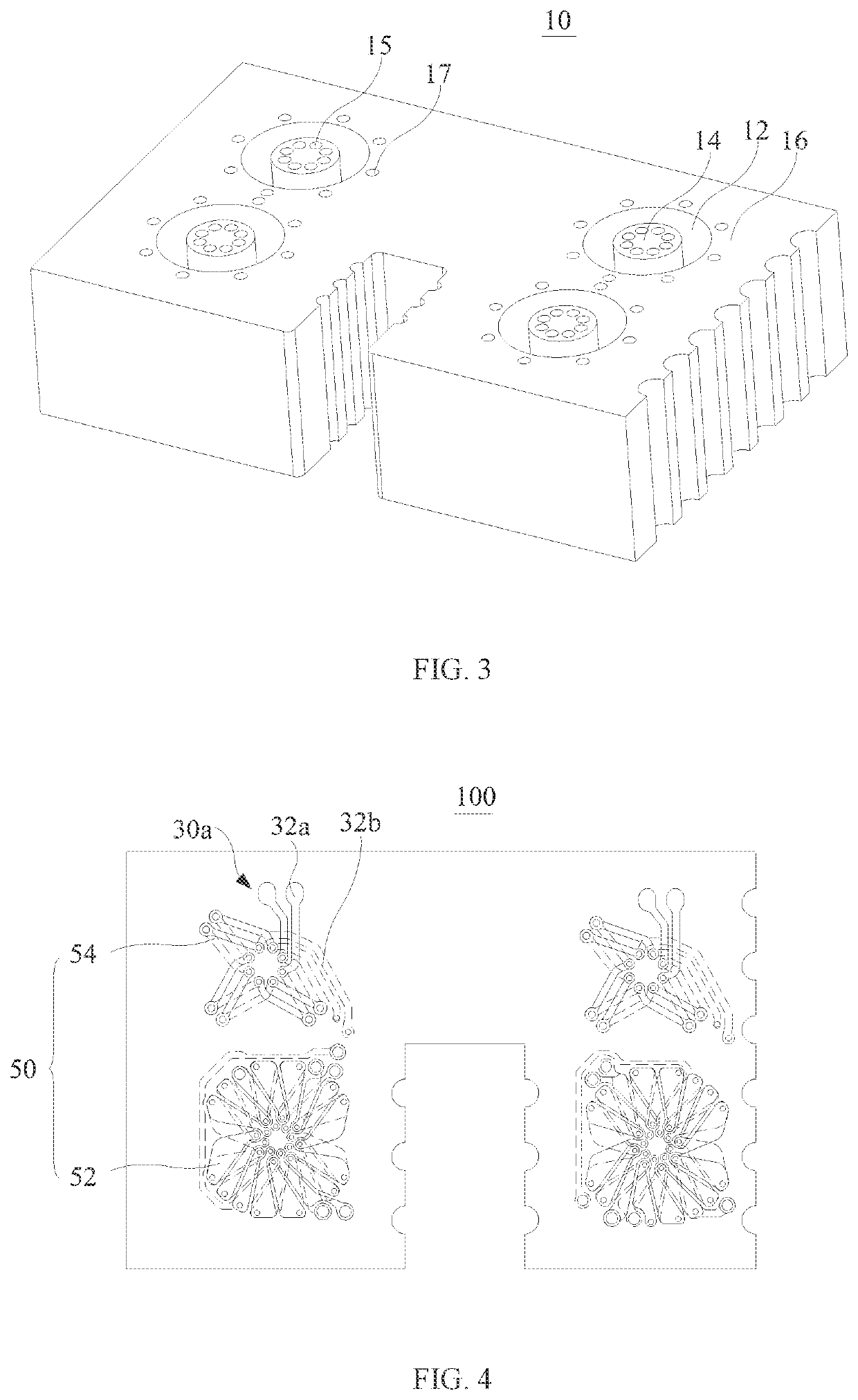
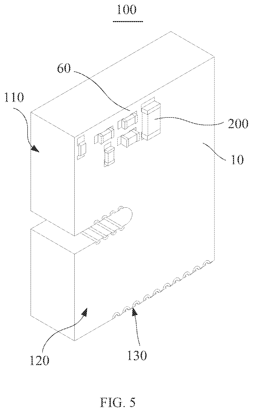
[0022]According to a first aspect of the present disclosure, an electromagnetic device is provided, wherein the electromagnetic device comprises: a substrate defining a plurality of annular receiving grooves, wherein each annular receiving groove divides the substrate into a central portion surrounded by the annular receiving groove and a peripheral portion surrounding the annular receiving groove, each central portion defines a plurality of inner via holes running through the substrate, and each peripheral portion defines a plurality of outer...


PUM

PropertyMeasurementUnit
included angleaaaaaaaaaa
thicknessaaaaaaaaaa
thicknessaaaaaaaaaa

Abstract

An electromagnetic device includes a substrate, magnetic cores, transmission line layers, and conductive members. The substrate is provided with annular receiving grooves for accommodating the magnetic cores; the substrate is divided into a central portion and a peripheral portion; inner and outer via holes are respectively formed on the central portion and the peripheral portion, respectively; the transmission line layers each including wire patterns are respectively provided on opposite sides of the substrate; and the conductive members are sequentially connected to the wire patterns on both sides of the substrate to form a transformer and / or a filter; the electromagnetic device has a first side provided with a slot and a second side parallel to the transmission line layers; and first conductive pins electrically connected to the at least one transmission line layers are provided on at least one of the side wall surrounding the slot and a second side.

Description

CROSS-REFERENCE TO RELATED APPLICATIONS[0001]The present disclosure is a continuation-application of International (PCT) Patent Application No. PCT / CN2018 / 094350 filed on Jul. 3, 2018, the entire contents of which are hereby incorporated by reference in their entireties.TECHNICAL FIELD[0002]The present disclosure relates to the technical field of integrated circuits, and in particular, to an electronic device, a connector, and an electromagnetic device thereof.BACKGROUND[0003]A connector is a component used to realize electrical connection between two different devices, playing the role of a switch and a bridge. As a signal transmission medium, it has become an indispensable component in modern equipment. A connector at least includes an electromagnetic device and a connector assembly which are electrically connected. The electromagnetic device is used to perform signal processing (for example, perform transforming and / or filtering processing) for signals transmitted between two dev...

Claims


Application Information

Patent Timeline
Patent Type & Authority Applications(United States)
IPC IPC(8): H01F27/29H01F27/28H01F27/06H01R12/57H05K1/18H03H1/00
CPCH01F27/29H01F27/2804H01F27/06H01R12/57H01R24/64H03H1/0007H01F2027/2814H01F2027/065H05K1/181H01R13/6658H01F27/2895H03H7/0115H03H2001/0092H05K2201/1006H05K2201/10522
Inventor GUO, WEIJINGZENG, YUHUAMIAO, HUAQUILICI, JAMES
Owner SHENNAN CIRCUITS
Learn More