Method and device for monitoring a bearing equipping a rotary device

a technology of a rotary device and a bearing, which is applied in the direction of machine parts testing, structural/machine measurement, instruments, etc., can solve the problems of untimely stopping of the machine in which it is used, untimely stopping of the current monitoring system implementing vibration analysis, and several practical difficulties, so as to improve the earliness of defect detection, reduce the effectiveness of estimation errors, and increase the estimating error marring the computed indicator

Active Publication Date: 2021-03-04
SAFRAN
View PDF0 Cites 4 Cited by
  • Summary
  • Abstract
  • Description
  • Claims
  • Application Information

AI Technical Summary

Benefits of technology

[0032]It will be noted that the indicator derived in accordance with the invention is determined for a given defect liable to affect the bearing since it depends on an actual frequency of the defect estimated on the basis of the characteristic theoretical frequency of the defect and of a determined maximum deviation around this theoretical frequency, each defect manifesting as a different theoretical frequency and as a maximum possible deviation of the actual frequency of the defect with respect to this theoretical frequency. Thus, by deriving several indicators relating to a plurality of defects liable to affect the bearing (e.g. an indicator associated with a defect on the inner bush of the bearing, an indicator associated with a defect on the outer bush of the bearing, an indicator associated with a defect on the cage of the bearing, an indicator associated with a defect on a rolling element of the bearing etc.), it is possible to easily identify the element or elements of the bearing that have a defect. This makes it possible to effect targeted maintenance on the bearing.
[0069]This makes it possible to have appropriate maintenance of the monitored bearing.

Problems solved by technology

Due to their elementary role in mechanical transmission systems, bearings are constantly stressed and therefore embrittled.
Damage to a bearing can lead to an untimely stopping of the machine in which it is used.
However, current monitoring systems implementing vibrational analysis encounter several practical difficulties.
The result of this is that the component representing the defect can be masked by noise coming from other sources of extraneous vibration (i.e. other rotary elements of the equipment item under consideration), so that the methods used in current monitoring systems (for example envelope analysis) are not always capable of detecting this defect.
This can lead to the late detection of the defect, or even an inability to detect the defect.
However, these techniques have a high computing cost, and are often impossible to implement in real time.
Furthermore, a particular difficulty that arises when bearings are monitored by vibrational analysis is that the actual frequencies of the defects affecting these bearings can differ from the theoretical values computed for the requirements of vibrational analysis on the basis of the geometrical features of the bearing and its kinetics.
This is due to the slippage of the bearings on the one hand, and on the other hand, the fact that damage to the bearing is generally accompanied by a phenomenon of friction which tends to slow down the rotation of the damaged bearing and modify its kinetics.
However this method of detection has a relatively high complexity in terms of implementation, particularly due to the preprocessing carried out.
Furthermore, the effectiveness of the preprocessing carried out depends for the most part on the determination of several parameters (e.g. order of the autoregressive filter, etc.) which can turn out to be complicated in practice.

Method used


Image

  • Method and device for monitoring a bearing equipping a rotary device
  • Method and device for monitoring a bearing equipping a rotary device

Examples


Embodiment Construction

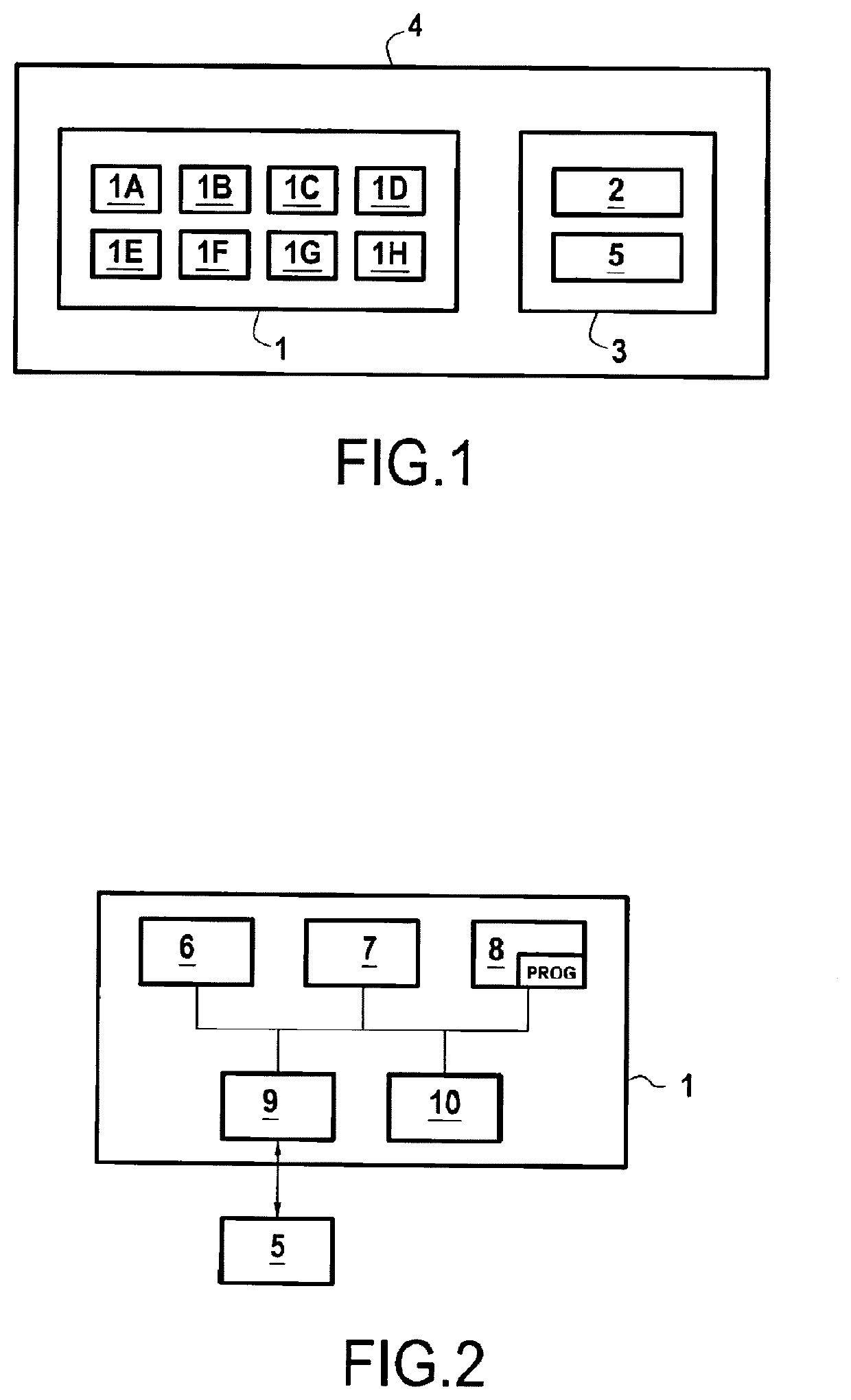
[0081]FIG. 1 shows, in its environment, a device 1 for monitoring a bearing 2 equipping a rotary mechanical device 3 in accordance with the invention in a particular embodiment.

[0082]In the example envisioned in FIG. 1, the bearing 2 is a ball bearing and the rotary device 3 equipped with this ball bearing is for example a compressor of a turbojet engine 4 in accordance with the invention. The bearing 2 is here assumed to permit the driving in rotation of a shaft of the compressor 3 of the turbojet engine 4 about a predefined axis of rotation.

[0083]This example is however given only by way of illustration, and the invention can also be applied to other contexts. Thus for example, the bearing 2 can be a roller bearing, the rotary device 3 can be any rotary mechanical device, an element of which is driven in rotation by means of the bearing 2, and other aircraft engines than a turbojet engine can be envisioned. The invention can also be applied to another context than the aeronautical...


PUM


Abstract

A method includes obtaining a vibration signal acquired by an accelerometer sensor; eliminating a deterministic component of the vibration signal; obtaining, for a determined defect, a characteristic theoretical frequency of this defect and a determined maximum deviation around this theoretical frequency; computing, as a function of a cyclic frequency, an integrated cyclic coherence of the processed vibration signal; estimating an actual frequency of the defect on the basis of the integrated cyclic coherence, of the theoretical frequency of the defect and of the maximum deviation; computing a diagnostic indicator of the defect by summing M integrated cyclic coherences of the vibration signal evaluated as M cyclic frequencies respectively equal to M harmonics of the estimated actual frequency of the defect; comparing the diagnostic indicator of the defect with a predetermined threshold, and in the event of it being exceeded, detecting the defect on the bearing.

Description

BACKGROUND OF THE INVENTION[0001]The invention relates to the general field of rotary machines or devices, and more particularly relates to the bearings equipping such machines or devices, such as for example ball or roller bearings.[0002]It has a preferred but non-limiting application in the field of aeronautics in which many rotary machines are used.[0003]Bearings, and in particular ball or roller bearings, are rotary mechanical devices widely used in rotary machines and the role of which is to drive transmission shafts in rotation. Such a bearing is generally composed of two coaxial bushes (an inner bush and an outer bush) between which are placed rolling elements (balls or rollers), retained in a cage. The rotary movement of the shaft is provided by the movement of the rolling elements.[0004]Due to their elementary role in mechanical transmission systems, bearings are constantly stressed and therefore embrittled. They can undergo degradation of the surface condition or the shape...

Claims


Application Information

Patent Timeline
Patent Type & Authority Applications(United States)
IPC IPC(8): G01M13/045G01M15/14
CPCG01M13/045G01M15/14G01M15/12G01H1/003
Inventor ABBOUD, DANYEL BADAOUI, MOHAMED
Owner SAFRAN
Why Eureka
Try Eureka