
Method of driving a display panel

a display panel and display panel technology, applied in the field of display panel driving, can solve the problems of reducing the life of the unit pixels in the low resolution display region, affecting the image quality affecting the viewing experience of the viewing device, so as to reduce the luminance of the first display region, reduce the deterioration of the unit pixels, and reduce the effect of luminance differen

Active Publication Date: 2021-03-04
SAMSUNG DISPLAY CO LTD
View PDF0 Cites 9 Cited by
  • Summary
  • Abstract
  • Description
  • Claims
  • Application Information

AI Technical Summary

Benefits of technology

The present disclosure provides a method of driving a display panel that can minimize or prevent a boundary between different display regions due to luminance differences between them. This is achieved by optimizing the luminance of the first display region using a gray-level of maximum luminance data applied to it. This method can also deterioration of the pixels in the first display region by reducing the luminance of the adjacent display region in a direction from the non-adjacent display region towards the first display region. As a result, the method prevents or minimizes image quality degradation due to the boundary between the first display region and the adjacent display region.

Problems solved by technology

Thus, due to a luminance difference may occur between the low resolution display region and the normal display region even under the same condition, a boundary between the low resolution display region and the normal display region may stand out, and thus a viewer (or user) may perceive image quality degradation due to existence of the low resolution display region.
However, the increased current may rapidly deteriorate and reduce life of the unit pixels in the low resolution display region, and thus a permanent afterimage or the like due to the deterioration may occur.

Method used


Image

  • Method of driving a display panel
  • Method of driving a display panel
  • Method of driving a display panel

Examples


Embodiment Construction

[0041]Hereinafter, some example embodiments of the present inventive concept will be explained in detail with reference to the accompanying drawings.

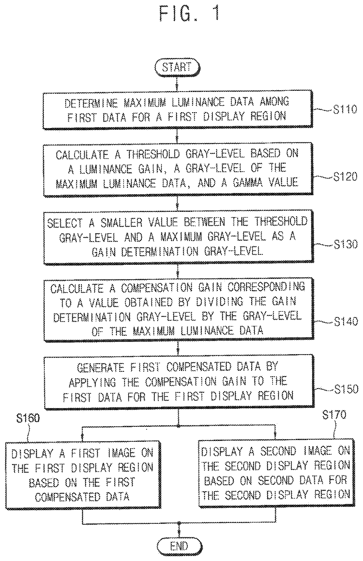
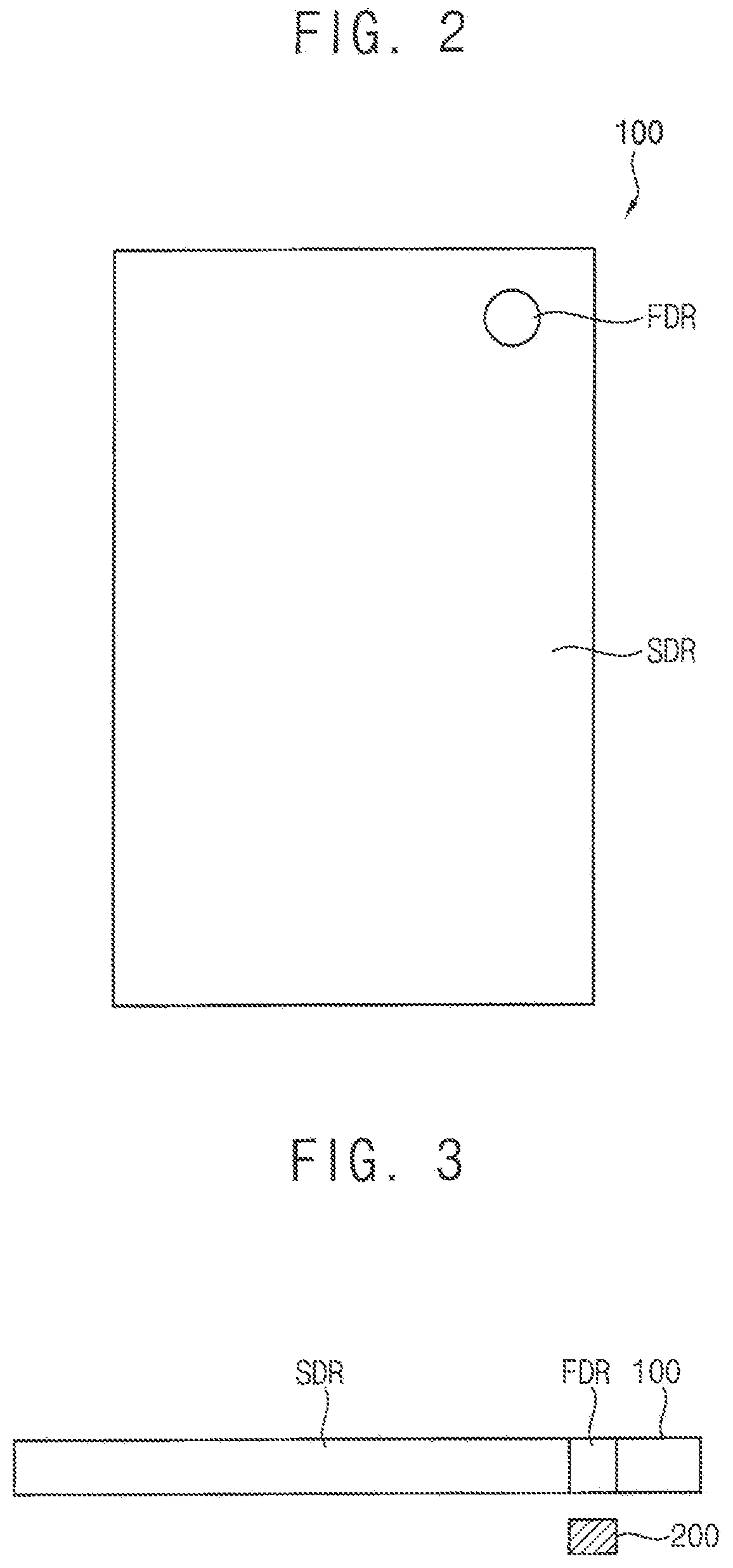
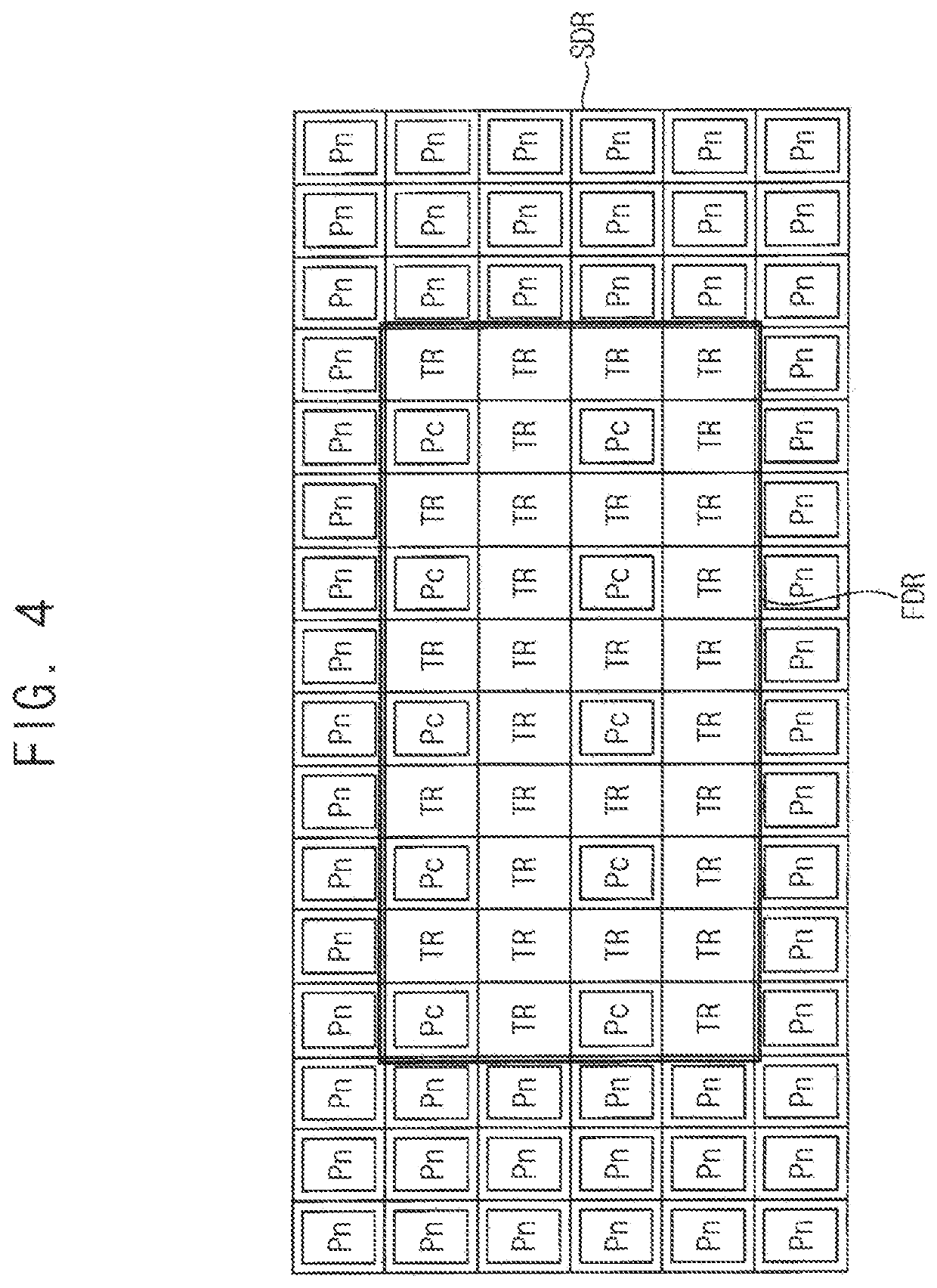
[0042]FIG. 1 is a flowchart illustrating a method of driving a display panel according to one embodiment, FIG. 2 illustrates an example of a display panel that is driven by the method of FIG. 1, FIG. 3 illustrates an example in which a camera module is disposed under the display panel of FIG. 2, and FIG. 4 illustrates an example of first and second display regions included in the display panel of FIG. 2.

[0043]Referring to FIGS. 1, 2, 3, and 4, the method of FIG. 1 may be applied to drive the display panel 100 that includes a first display region FDR having a first resolution in which at least one transparent region TR is located and a second display region SDR having a second resolution higher than the first resolution. The method of FIG. 1 may include determining maximum luminance data among first red data, first green data, and first ...


PUM


Abstract

A method of driving a display panel that includes first and second display-regions includes: determining maximum luminance data among first data including first red data, first green data, and first blue data for the first display-region, calculating a threshold gray-level based on a luminance gain, a gray-level of the maximum luminance data, and a gamma value for the display panel, selecting a smaller value between the threshold gray-level and a maximum gray-level as a gain determination gray-level, calculating a compensation gain obtained by dividing the gain determination gray-level by the gray-level of the maximum luminance data, generating first compensated data by applying the compensation gain to the first data, displaying a first-image in the first display-region based on the first compensated data, and displaying a second-image in the second display-region based on second data including second red data, second green data, and second blue data for the second display-region.

Description

CROSS-REFERENCE TO RELATED APPLICATION(S)[0001]This application claims priority under 35 USC § 119 to Korean Patent Application No. 10-2019-0106389, filed on Aug. 29, 2019 in the Korean Intellectual Property Office (KIPO), the disclosure of which is incorporated herein in its entirety by reference.BACKGROUND1. Technical Field[0002]The present inventive concept relates generally to a method of driving a display panel. More particularly, the present inventive concept relates to a method of driving a display panel that includes a first display region having a first resolution in which at least one transparent region is located and a second display region having a second resolution that is higher than the first resolution2. Description of the Related Art[0003]As consumers put an importance on an exterior design of an electronic device (e.g. smartphone, etc.), technologies have been developed for providing a hole in a display panel of an electronic device to dispose a camera module (i.e....

Claims


Application Information

Patent Timeline
Patent Type & Authority Applications(United States)
IPC IPC(8): G09G3/20
CPCG09G3/2003G09G3/2007G09G2320/0242H04N5/2257G09G2340/0407G09G2320/0686G09G2320/046G09G2320/0233G09G3/20G09G2320/0271G09G2360/16G09G2310/0232H04N23/57
Inventor PARK, JONG-WOONG
Owner SAMSUNG DISPLAY CO LTD
Learn More