Cooling device and image forming system

a cooling device and cooling system technology, applied in the field of cooling devices, can solve the problems of non-uniformity of toner images, affecting the cooling effect of the image forming apparatus, and the temperature of the recording material fed from the cooling device, so as to enhance the cooling performance of the image forming apparatus, and suppress the sticking between the recording materials

Active Publication Date: 2021-03-11
CANON KK
View PDF0 Cites 9 Cited by
  • Summary
  • Abstract
  • Description
  • Claims
  • Application Information

AI Technical Summary

Benefits of technology

[0006]Further, for users utilizing the image forming apparatus provided with no cooling device, in the case where a recording material such as the thick paper needed to increase a fixing temperature is used, there was a liability that recording materials stacked on the stacking portion stick to each other. For such users, in order to uniformize the guide of the toner image and to suppress the sticking between the recording materials stacked on the stacking portion, a new replacement image forming apparatus provided with a cooling device has to be bought. For that reason, it is not easy for the user utilizing the image forming apparatus provided with no cooling device to enhance a cooling performance of the image forming apparatus.
[0007]The present invention has been accomplished in view of the above problem, and an object of the present invention is to provide a cooling device and an image forming system which are capable of enhancing the cooling performance of the image forming apparatus.

Problems solved by technology

The recording material is heated when the toner image is fixed, and therefore, the recording material fed from the fixing device is liable to increase in temperature compared with before the fixation.
Then, after the toner image is fixed, when the toner image is fed and discharged while being kept at a temperature higher than a predetermined temperature, there is a liability that glossiness of the toner image becomes non-uniform with feeding or that recording materials stacked on a stacking portion stick to each other by toner.

Method used


Image

  • Cooling device and image forming system
  • Cooling device and image forming system
  • Cooling device and image forming system

Examples


Embodiment Construction

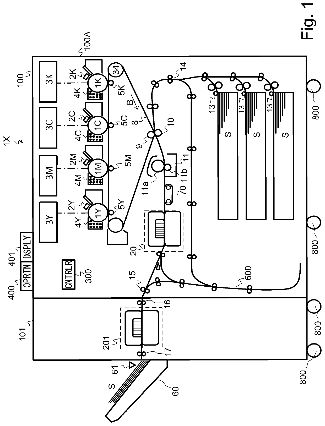
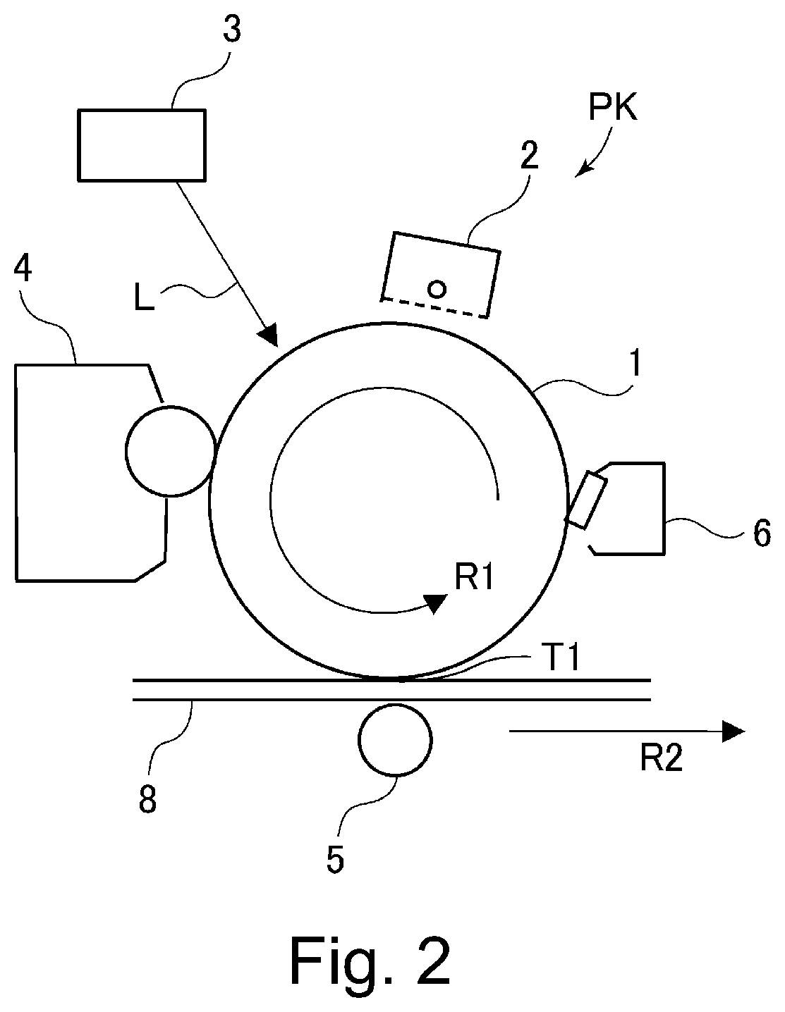
[0023]A schematic structure of an image forming system of this embodiment will be described using FIGS. 1 and 2. An image forming system 1X of this embodiment includes, as shown in FIG. 1, an image forming apparatus 100 for forming an image on a recording material S and an external cooling device 101 for cooling the recording material S on which the image is formed on the recording material S by the image forming apparatus 100.

[0024]The image forming apparatus 100 shown in FIG. 1 is an electrophotographic full-color printer of a tandem type. The image forming apparatus 100 includes image forming portions PY, PM, PC and PK for forming images of yellow, magenta, cyan and black, respectively. The image forming apparatus 100 forms a toner image on a recording material S in response to an image signal sent from an original reading device (not shown) connected to an apparatus main assembly 100A or from an external device such a personal computer communicatably connected to the apparatus m...


PUM


Abstract

An external cooling device 101 is connectable to an image forming apparatus 100. The external cooling device 101 improves cooling power of a recording material S after toner image fixation. In this case, even when a heating amount of the fixing device 11 is increased, a temperature of the recording material S stacked on a stacking unit 60 can be lowered to not more than a predetermined temperature at which sticking does not occur. Further, the number of sheets stackable on said stacking unit 60 can be increased. By this, a user is capable of adjusting glossiness without concern for the sticking of the recording materials S on the stacking unit 60. Further, the user is not required to frequently carry out the recording material S of the stacking unit 60. That is, it is possible to provide an image forming system 1X capable of flexibly meeting the recording materials S of various kinds.

Description

TECHNICAL FIELD[0001]The present invention relates to a cooling device, for cooling function expansion, capable of being connectable to an image forming apparatus, such as a printer, a copying machine, a facsimile machine or a multi-function machine, using an electrophotographic type.BACKGROUND ART[0002]In an image forming apparatus of the electrophotographic type, a toner image formed on a recording material such as paper is fixed on the recording material by being heated and pressed by a fixing device. Fixation of the toner image is carried out by nipping and feeding the recording material by a fixing roller heated by a heater or the like and a pressing roller press-contacted to the fixing roller. The recording material is heated when the toner image is fixed, and therefore, the recording material fed from the fixing device is liable to increase in temperature compared with before the fixation. Then, after the toner image is fixed, when the toner image is fed and discharged while ...

Claims


Application Information

Patent Timeline
Patent Type & Authority Applications(United States)
IPC IPC(8): G03G21/20G03G15/20
CPCG03G21/20H04N1/00981G03G15/2017G03G15/6573G03G15/6582G03G21/206G03G15/2021
Inventor INOUE, YUKIYOSHIDA, ATSUSHIHATAZAKI, KAZUNARICHIKUGO, YOUICHIKOYANAGI, NORIAKI
Owner CANON KK
Why Eureka
Try Eureka