Multi-Surface Cleaning Tool

Pending Publication Date: 2021-03-18
CHEN YONG S
View PDF4 Cites 0 Cited by
  • Summary
  • Abstract
  • Description
  • Claims
  • Application Information

AI Technical Summary

Benefits of technology

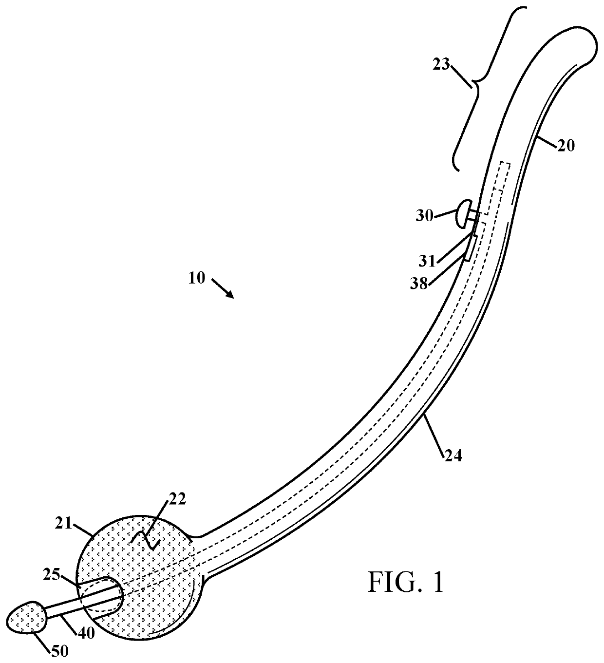
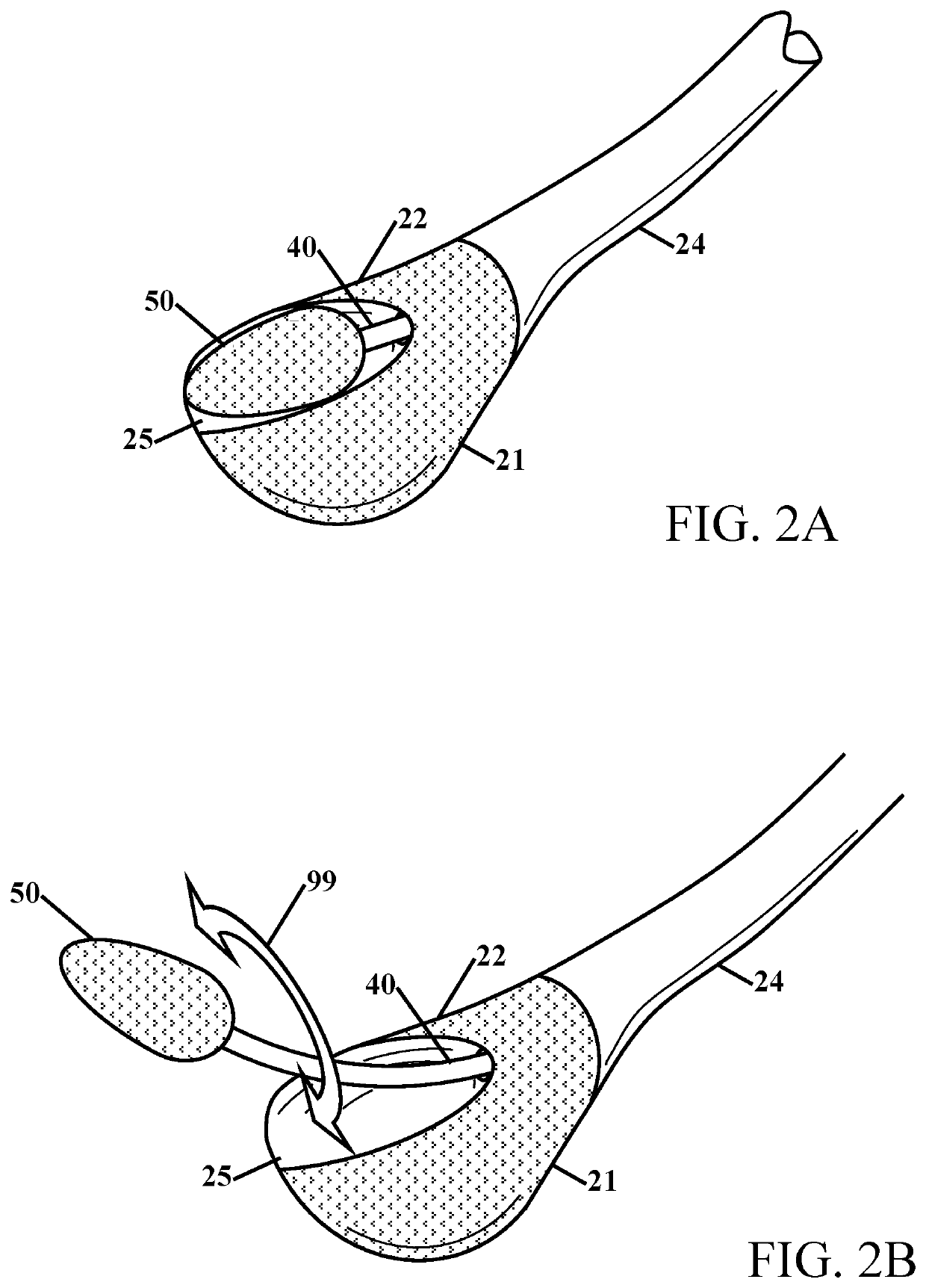
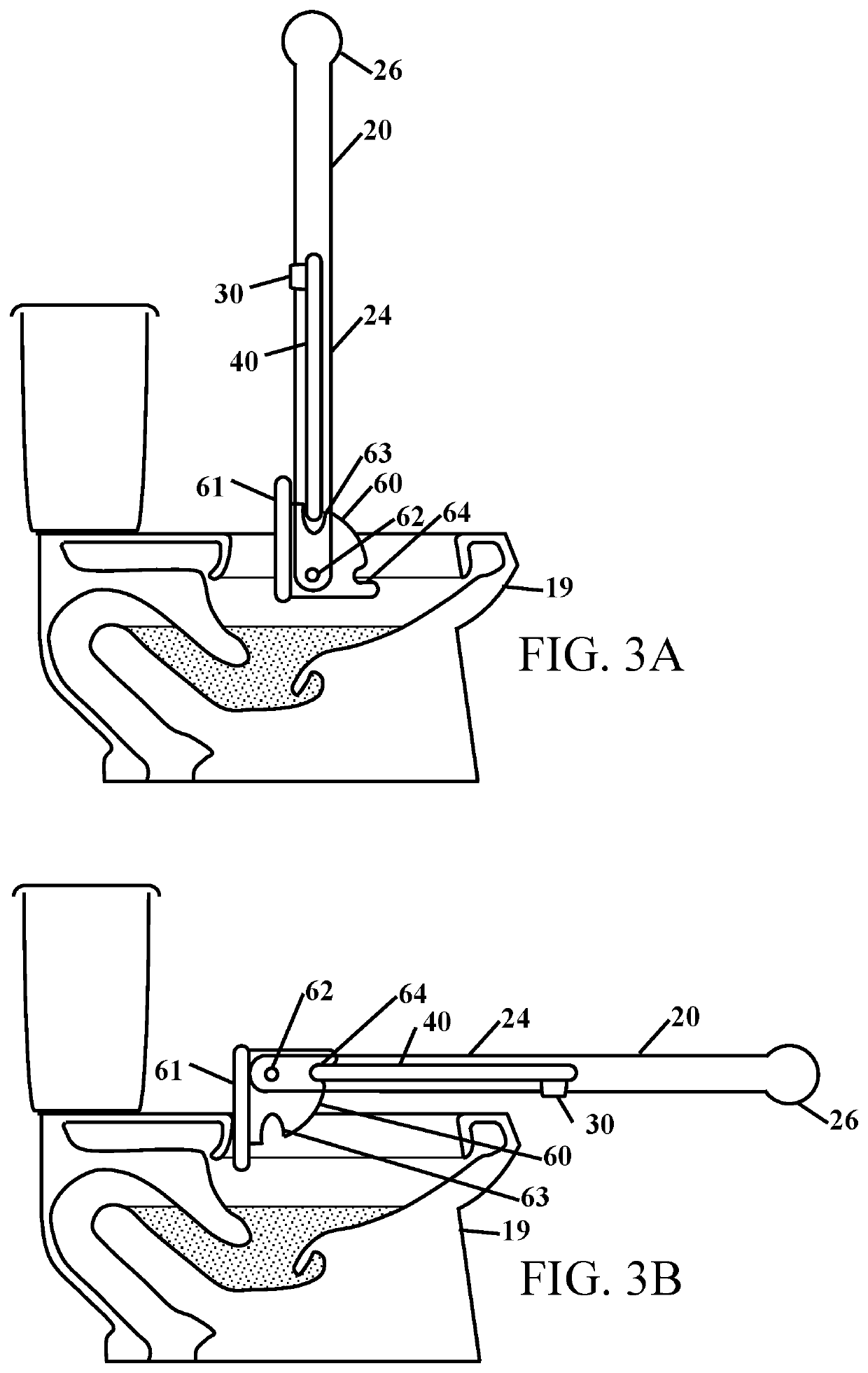
The multi-surface cleaning tool is designed to clean a variety of surfaces, including toilets, bathroom surfaces, sinks, and vehicle rims. It has a rotating head that allows for versatility and pressure cleaning. The tool also has a removable inner detailing head that can be retracted into the outer cleaning tool for easy storage. This tool has a handle that allows the user to reach into areas from a distance and clean the corners and cervices of surfaces. Overall, this tool provides efficient and effective cleaning for a variety of surfaces and areas.

Problems solved by technology

The brush has a handle that extends from the rear to enable a user to reach into areas from a distance and further reduces the potential for the splatter to reach beyond the distance of the handle.
In particular, corners that join at 90 degrees can be difficult reach, the detailing tool is tapered to reach these corners from a distance at the end of the handle.

Method used


Image

  • Multi-Surface Cleaning Tool
  • Multi-Surface Cleaning Tool
  • Multi-Surface Cleaning Tool

Examples


third embodiment

[0047]FIG. 6 show the movable detail cleaning head. The brush with detailing head 81 can have a first larger cleaning head 80 as a porous sponge type head, can have bristles, or a scrubber but can have a hybrid. The handle 26 has a fixed outer shaft 24. Within the outer shaft 24 is a movable inner shaft 77. At a first end of the movable inner shaft 77 is a button 30, at a second end of the movable inner shaft 77 is a smaller detail head 81. The detailing head 81 retracts to a position that is adjacent to the first larger cleaning head 80. Due to the size and shape of the larger cleaning head 80 the ability to clean in corners is limited. Extending the second smaller detail head 81 is activated from the upper portion of the handle 20. A user grips the handle end 26, as a user grips the handle, the user can place a thumb or other digit onto the button 30. The button 30 can then be pushed downward 94 where the user can extend and articulate the second smaller detail head 81.

fourth embodiment

[0048]FIG. 7 shows a rotating cleaning head. In this embodiment the dual cleaning head has a larger first end 82 and a smaller second end 83. The outer shaft 24 is essentially fixed and pivot point 86 allows the rotating cleaning head to pivot on the pivot point 86. The end of the fixed outer shaft 24 has an offset arm 87. The offset arm 87 can take a variety of shapes. One contemplated shape is shown in this figure. When the button 30 is moved down 94 it pushes movable inner shaft 77 down and pivots 85 in the slot 84 to move the smaller second end 83 of the cleaning head downward to allow use of the smaller second end 83 into a position for use.

fifth embodiment

[0049]FIG. 8 shows a rotating cleaning head. This cleaning tool has a rotating body 88 with two ends for cleaning heads. The rotating body rotates from a pivot points 72 and 73. To change orientations of the rotating body 88 the user can slide 96 the button 30 that raises the moving rod 76. The moving rod 76 has pivots 74 and 75 that allows the moving rod to flex, bend or pivot to change between the two cleaning heads.


PUM


Abstract

Improvements in a cleaning brush is disclosed. The cleaning tool has both a larger and smaller cleaning feature a single size cleaning tool to try and cover all uses is obviated. With a larger cleaning head, the larger cleaning head can be optimized for the rim surfaces of a toilet. The inner detailing head retracts into the outer cleaning tool. In the retracted mode the detailing head operates with the larger outer tool and provides a cohesive flat surface for cleaning. A spring can be used to retract the detailing head. The detailing head extends from the center, side or corner of the cleaning tool and extends far enough to allow for full use of the detailing head to effectively reach corners and / or cervices. The handle and or the head can be angled to provide an optimum angle for use.

Description

CROSS REFERENCE TO RELATED APPLICATIONS[0001]This application claims the benefit of Provisional Application Ser. No. 62 / 901,190 filed Sep. 16, 2019 the entire contents of which is hereby expressly incorporated by reference herein.STATEMENT REGARDING FEDERALLY SPONSORED RESEARCH OR DEVELOPMENT[0002]Not ApplicableTHE NAMES OF THE PARTIES TO A JOINT RESEARCH AGREEMENT[0003]Not ApplicableINCORPORATION-BY-REFERENCE OF MATERIAL SUBMITTED ON A COMPACT DISC[0004]Not ApplicableBACKGROUND OF THE INVENTIONField of the Invention[0005]This invention relates to improvements in a cleaning brush. More particularly, the present multi-surface cleaning tool has a brush with detailing head or rotating head that has a brush head that provides cleaning of larger areas and an internal smaller head or surface that can be extended or rotated from to provide detailed cleaning to corners or smaller areas.Description of Related Art Including Information Disclosed Under 37 CFR 1.97 and 1.98[0006]Toilets, sinks,...

Claims


Application Information

Patent Timeline
IPC IPC(8): A47K11/10A46B5/00
CPCA47K11/10A46B2200/304A46B5/0012A46B13/08A46B5/0083A46B9/005A46B9/06A46B5/005
Inventor CHEN, YONG S.
Owner CHEN YONG S
Why Eureka
Try Eureka