Glove, in particular goalkeeper glove

a glove and glove technology, applied in the field of glove, can solve the problems of hardly being able to precisely control the direction in which the ball is deflected by the fist, hardly being able to secure the ball, and being difficult for the goalkeeper to catch the ball securely, etc., to achieve greater restoring force, avoid the effect of third-party injuries caused by the protrusion and increasing the friction of the ball

Pending Publication Date: 2021-03-18
ADIDAS
View PDF9 Cites 1 Cited by
  • Summary
  • Abstract
  • Description
  • Claims
  • Application Information

AI Technical Summary

Benefits of technology

[0018]In some embodiments, an end portion—which by definition always faces a base of a protrusion in the first direction—of at least one protrusion may include a spherical, ellipsoidal or funnel shape. In this way, injuries to third parties by the protrusions may be avoided and / or the possible contact area of the at least one protrusion with a ball may be further adjusted, for example enlarged.
[0019]At least one protrusion may be adapted to abut against an adjacent protrusion when it is deformed in the second direction. This may be achieved, for example, by having end portions of protrusions include a larger diameter than a respective base, such as when the end portions include a spherical shape, an ellipsoidal shape or a funnel shape as just described. When adjacent protrusions abut against each other, they may support each other and thus develop a greater restoring force, which in turn may lead to increased friction with the ball and thus to improved ball control.
[0020]Also, protrusions—both for this purpose and in general—may differ in size, in particular height, shape and / or orientation. The height of a protrusion denotes its extension in the first direction. The orientation of a protrusion is the direction of its tilted orientation. The number of protrusions per unit area, i.e., the (distribution-)density of the protrusions, may also be varied across the backside of the glove. This allows a high degree of flexibility in the design of a, so that it may be adapted to the respective purposes and needs. For example, the size, shape, orientation and / or (distribution-)density of the protrusions may be varied at will—if necessary even individually for a particular wearer—in order to take greater advantage of the above-described beneficial effects of the deformable, tilted protrusions in certain areas of the glove and / or in certain directions than in others.
[0021]It may be particularly advantageous to provide the protrusions in the area of the knuckles, as this is the area that typically comes into contact with the ball when fisting away. But also in the area of the backside of the hand and / or in the area of the thumb, in particular in the area of the base joint of the thumb, the deformable, tilted protrusions may be advantageous, because the wearer of the glove cannot always hit the ball with the knuckles in front. In some situations, the ball will hit the backside of the hand or even the outside of the thumb. It may be important that a glove also allows a high degree of ball control in such cases, which may be ensured by protrusions in these areas.
[0022]Additionally or alternatively, at least one protrusion may also be curved. This may also favor that the respective protrusion may be more easily deformed by the ball, for example tilted, sheared or bent, and still build up sufficient restoring force.
[0023]Also, each protrusion may be individually attached to the backside of the glove, so protrusions do not protrude from a common base element. Not only may the above-mentioned freedom of design be further increased. It also makes it easier to repair or replace individual protrusions, which may have a positive effect on the durability and environmental friendliness of the gloves. In particular, it may also be avoided that a flat base element (from which the plurality of protrusions would then protrude) has to be attached to the glove, which could restrict the freedom of movement of the hand. If each protrusion is individually attached to the backside of the glove, the wearing comfort of the glove may be increased without the protrusions losing any functionality.

Problems solved by technology

However, in some game situations it may be hardly possible for the goalkeeper to catch the ball securely, for example when the ball is flying at some height or the goalkeeper is too far away from the ball to reach it with both hands.
However, such a fisting away offers considerably less control than a catching.
Also, the direction in which the ball is deflected by the fisting away may hardly be controlled sufficiently exactly.
The goalkeeper risks with a fisting-away and the resulting lack of ball control that the ball jumps directly in front of the opponent's feet or is not deflected at all.

Method used


Image

  • Glove, in particular goalkeeper glove
  • Glove, in particular goalkeeper glove
  • Glove, in particular goalkeeper glove

Examples


Embodiment Construction

[0043]For the sake of brevity, only a few embodiments will be described below. The person skilled in the art will recognize that the features described with reference to these specific embodiments may be modified and combined in different ways and that individual features may also be omitted. The general explanations in the sections above also apply to the more detailed explanations below.

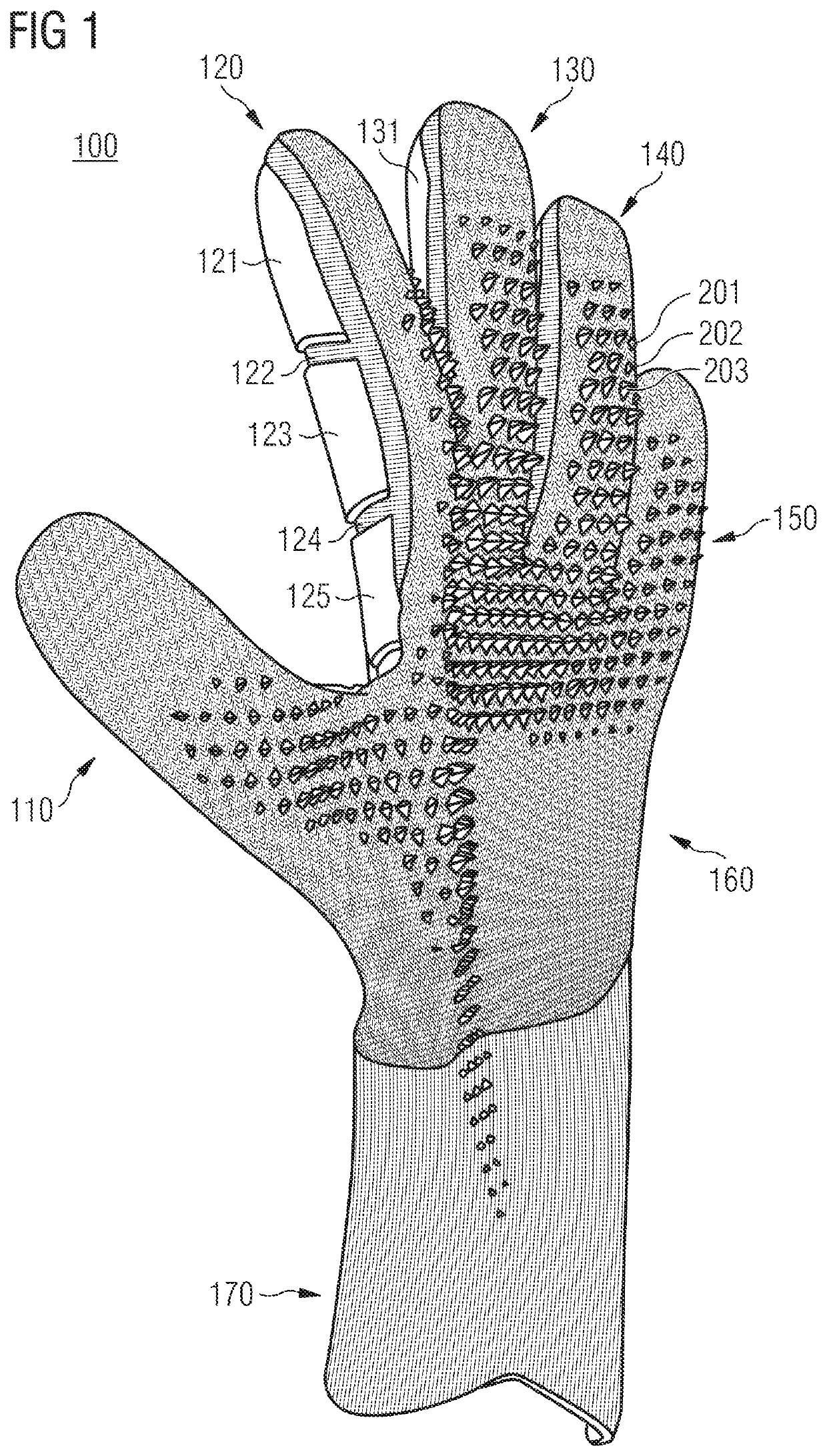
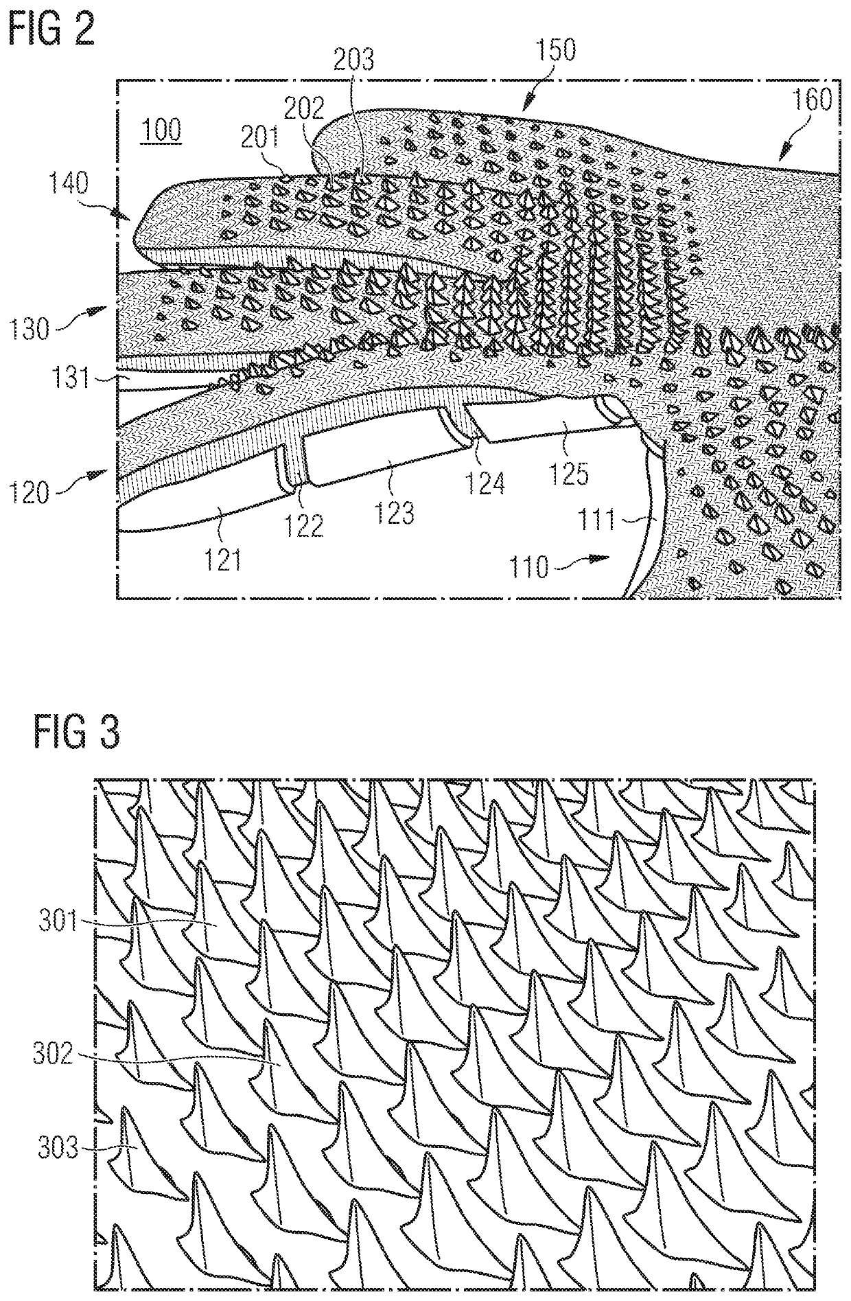
[0044]FIG. 1 shows an embodiment of a goalkeeper glove 100. The glove 100 includes a thumb 110, an index finger 120, a middle finger 130, a ring finger 140 and a pinkie 150, the backsides of which are visible in FIG. 1. The backside of a finger or of a glove as a whole denotes the side facing away from the palm of the wearer's hand when the glove is worn. In particular, such a backside is therefore also turned away from the palm of the wearer's hand when he is wearing the glove. The glove 100 further includes a backside of the hand area 160 and a wrist area 170.

[0045]The glove 100 includes one or m...


PUM


Abstract

A glove, in particular a goalkeeper glove. The glove includes a plurality of protrusions that protrude from a backside of the glove and extend in a first direction away from the backside. The protrusions are adapted to deform in a second direction that includes a component perpendicular to the first direction.

Description

TECHNICAL FIELD[0001]The present invention relates to a glove, in particular a goalkeeper glove.STATE OF THE ART[0002]Gloves have been known for a long time in many different forms. On the one hand, gloves may serve to protect the hands from a number of environmental influences such as cold, heat or friction. In particular, gloves may protect the hands from injuries caused by chemical or physical impacts, such as blows or cuts. For example, flexible elements are known from EP 2 901 875 B1, which may be applied to gloves to protect the hand from the effects of pressure. Preferably, the elements are each designed in the shape of a pyramid comprising a recess at the top such that the lateral surfaces of the pyramid-shaped element may fold inwards when the elements are subjected to pressure acting vertically on them. From U.S. Pat. No. 10,342,274 B2, another type of protective element is known, which may be applied in the area of the backsides of the fingers in particular. On the other ...

Claims


Application Information

Patent Timeline
Patent Type & Authority Applications(United States)
IPC IPC(8): A63B71/14
CPCA63B71/148A63B2243/0025A63B71/141A63B2209/00
Inventor PECHTOLD, ANDRE
Owner ADIDAS
Why Eureka
Try Eureka