
Robotic end effector system with surface tracking and methods for use

a technology surface tracking, which is applied in the direction of arms, manufacturing tools, instruments, etc., can solve the problems of more complicated than desired programing of robotic end effectors, and difficulty or time-consuming in moving robotic end effectors within a manufacturing environmen

Active Publication Date: 2021-03-18
THE BOEING CO
View PDF0 Cites 10 Cited by
  • Summary
  • Abstract
  • Description
  • Claims
  • Application Information

AI Technical Summary

Benefits of technology

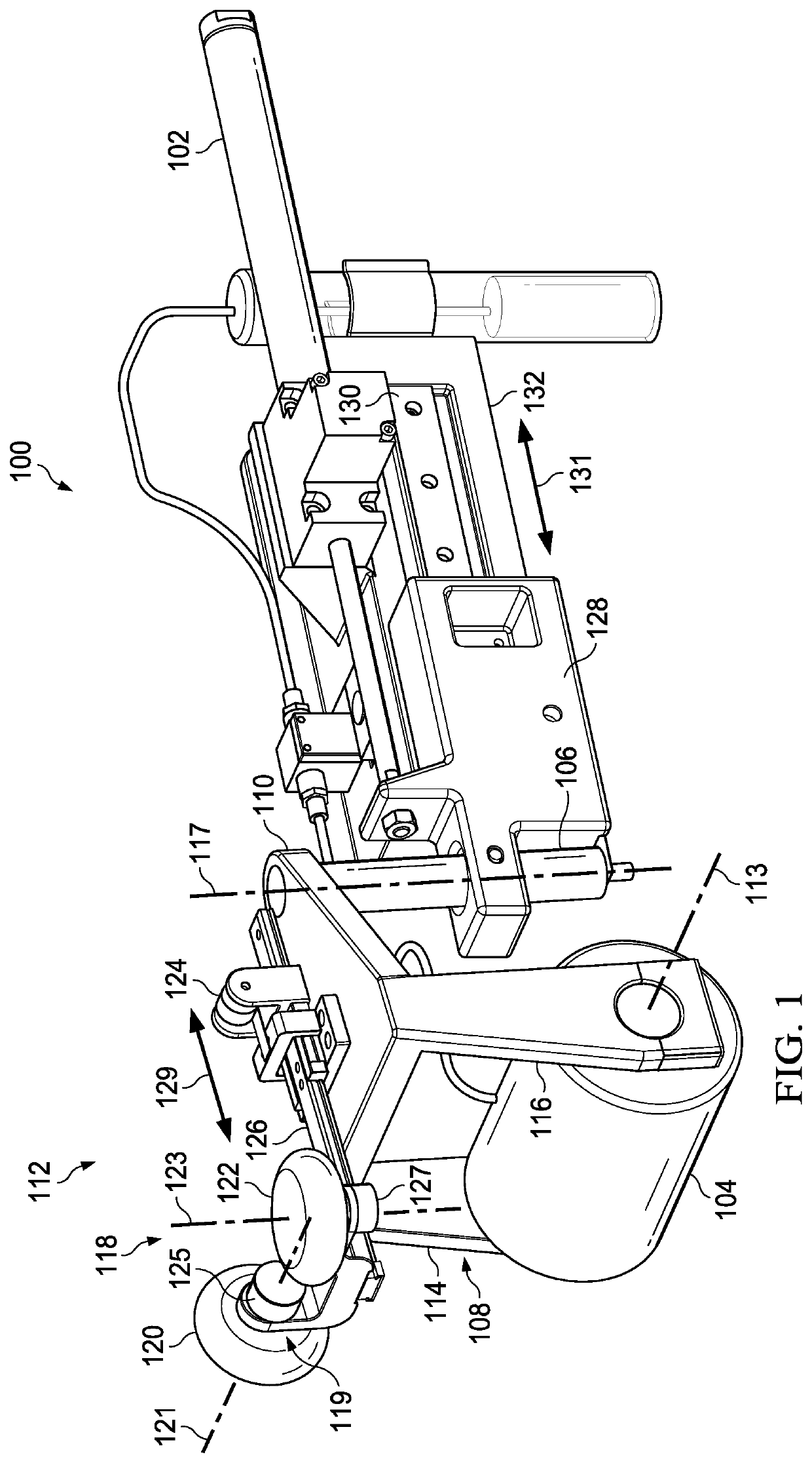
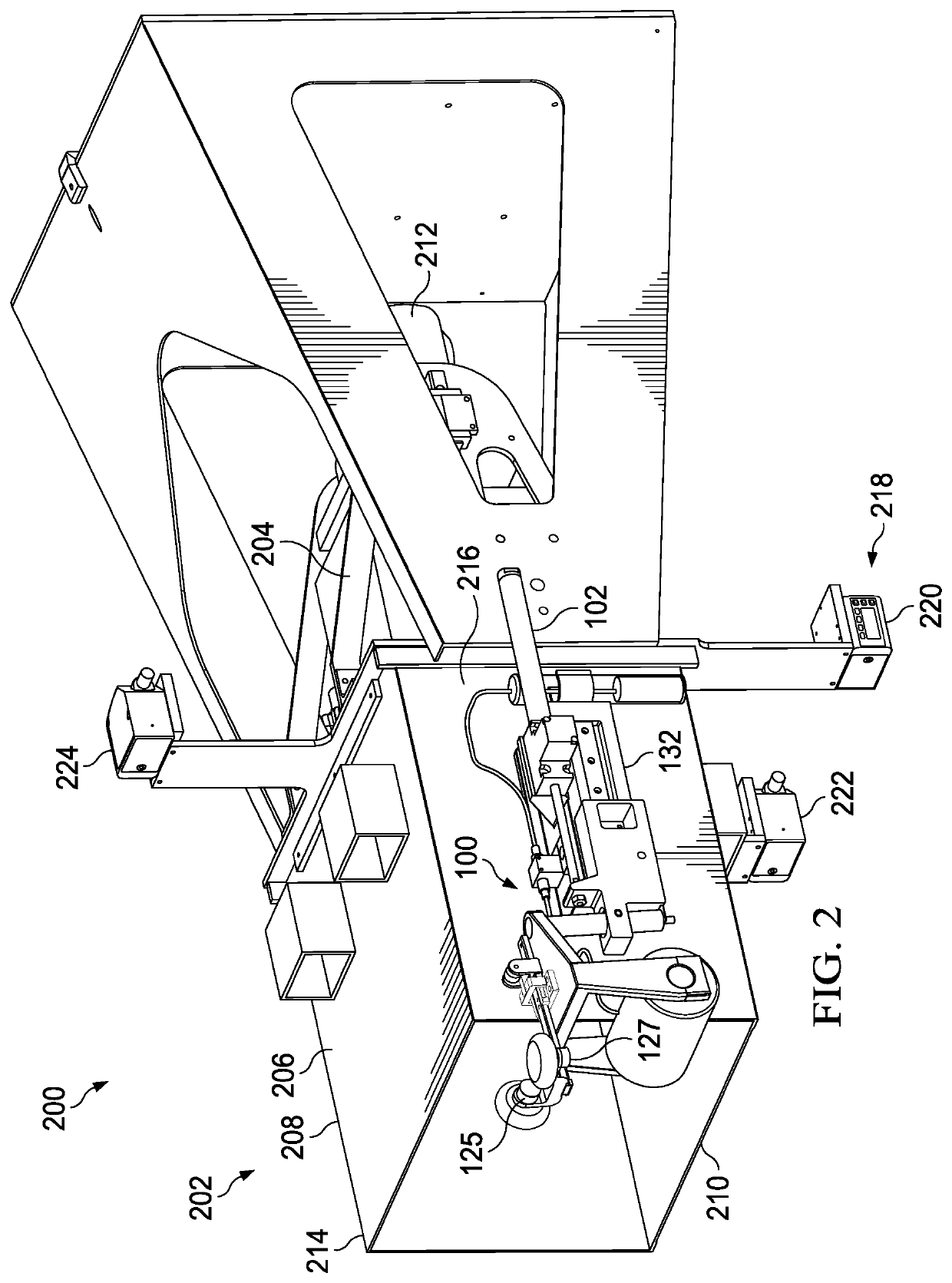
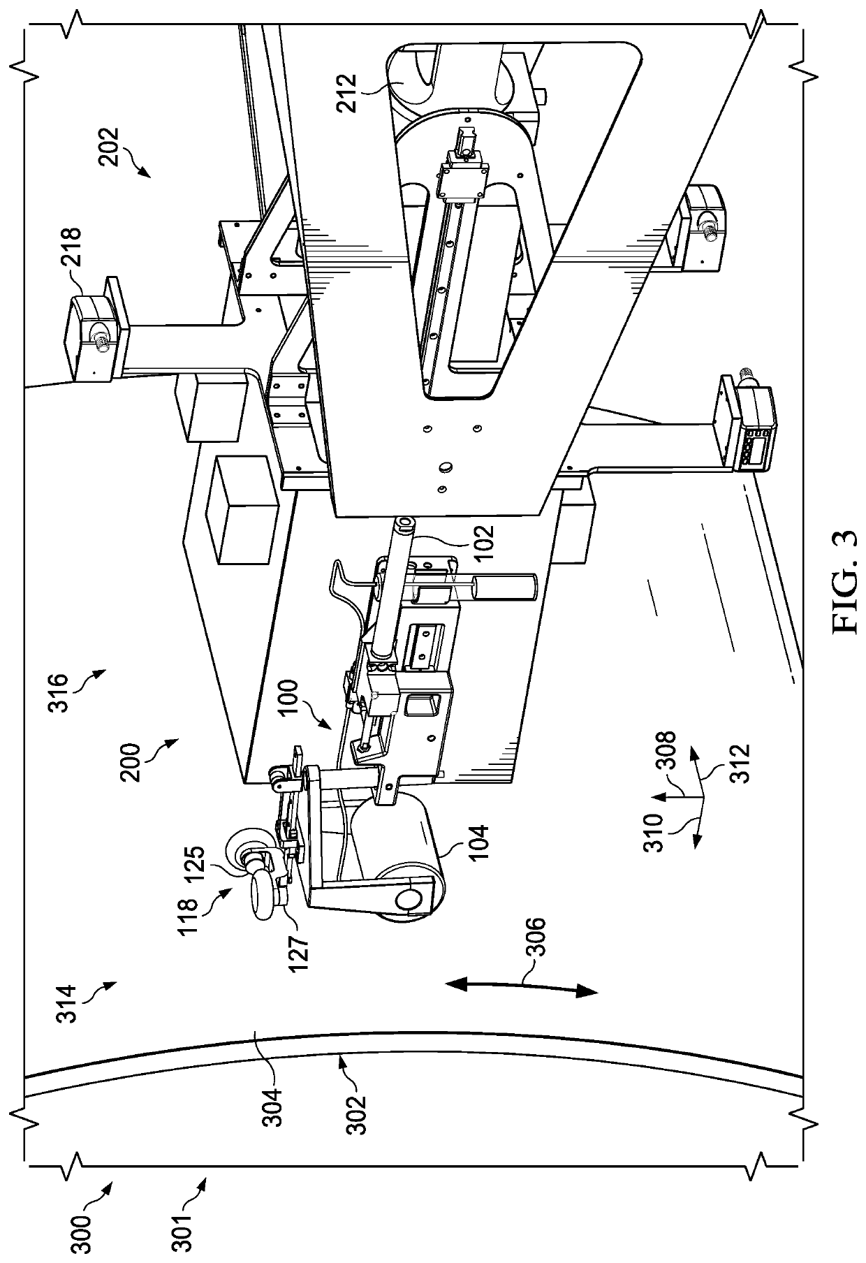
The present disclosure provides a non-destructive inspection system that uses an extendable actuator and a flange-mounted roller containing an ultrasonic sensor to inspect the condition of a structure. The system can roll the flange-mounted roller across the inspection surface to gather ultrasonic inspection data. The system can also use distance sensors and rotational angle sensors to determine its position and move to the desired vertical and horizontal positions. The technical effects of this system include improved inspection efficiency and accuracy, reduced human labor, and the ability to inspect difficult-to-reach surfaces.

Problems solved by technology

Moving robotic end effectors within a manufacturing environment may be more difficult or time-consuming than desired.
Some movement systems for robotic end effectors, including non-destructive inspection systems, may be more complicated than desired to program.

Method used


Image

  • Robotic end effector system with surface tracking and methods for use
  • Robotic end effector system with surface tracking and methods for use
  • Robotic end effector system with surface tracking and methods for use

Examples


Embodiment Construction

[0029]The illustrative embodiments recognize and take into account one or more different considerations. For example, the illustrative embodiments recognize and take into account that aircraft are being designed and manufactured with greater and greater percentages of composite materials. The illustrative embodiments recognize and take into account that composite materials are used in aircraft to decrease the weight of the aircraft. This decreased weight improves performance features such as payload capacities and fuel efficiencies. Further, composite materials may provide longer service life than some other materials for various components in an aircraft.

[0030]The illustrative embodiments recognize and take into account that composite materials are tough, lightweight materials created by combining two or more functional components. For example, the illustrative embodiments recognize and take into account that a composite material may include reinforcing fibers bound in polymer resi...


PUM


Abstract

A non-destructive inspection system is presented. The non-destructive inspection system comprises a robotic end effector having an extendable actuator and a flange-mounted roller containing an ultrasonic sensor, the flange-mounted roller connected to the extendable actuator by a pivot connection, the extendable actuator configured to extend the flange-mounted roller until the flange-mounted roller contacts an inspection surface.

Description

GOVERNMENT CONTRACT[0001]The invention described herein was made in the performance of work under NASA Contract No. NNL09AA00A and is subject to the provisions of Section 305 of the National Aeronautics and Space Act of 1958 (72 Stat.435: 42 U.S.C. 2457.)BACKGROUND INFORMATION1. Field[0002]The present disclosure relates generally to robotic end effectors. More specifically, the present disclosure relates to an apparatus and method for movement of robotic end effectors relative to an inspection surface. Also, the present disclosure relates to an apparatus and method for performing non-destructive inspections.2. Background[0003]Moving robotic end effectors within a manufacturing environment may be more difficult or time-consuming than desired. Additionally, prior knowledge, such as a three-dimensional model or surface scan of a structure, may be used to create a motion plan to move a robotic end effector relative to a surface of the structure. Some movement systems for robotic end eff...

Claims


Application Information

Patent Timeline
Patent Type & Authority Applications(United States)
IPC IPC(8): B25J9/16B25J15/00B25J19/02B25J17/02B25J18/02
CPCB25J9/1684B25J15/0019B25J19/026B25J19/021B25J19/02B25J18/02B25J17/0241B64F5/60G01N2291/2694G01N2291/0231G01N29/225G01N29/265B64C1/12B64C2001/0072Y02T50/40
Inventor TROY, JAMES J.WRIGHT, DANIEL JAMESLEA, SCOTT WESLEYTAPIA, WILLIAM JOSEPHGEORGESON, GARY ERNEST
Owner THE BOEING CO
Learn More