Spinal fixation device with rotatable connector

a fixation device and spindle technology, applied in the direction of osteosynthesis devices, internal osteosynthesis, internal osteosynthesis, etc., can solve the problems of pain for patients, affecting the healing of bony fusion, and requiring revision surgery, etc., to achieve the effect of convenient surgery, convenient surgery, and convenient rod placemen

a fixation device and spindle technology, applied in the direction of osteosynthesis devices, internal osteosynthesis, internal osteosynthesis, etc., can solve the problems of pain for patients, affecting the healing of bony fusion, and requiring revision surgery, etc., to achieve the effect of convenient surgery, convenient surgery, and convenient rod placemen

US20210085372A1Active Publication Date: 2021-03-25KOUTSOUMBELIS STELIOS

Image

  • Spinal fixation device with rotatable connector
  • Spinal fixation device with rotatable connector
  • Spinal fixation device with rotatable connector

Examples


Embodiment Construction

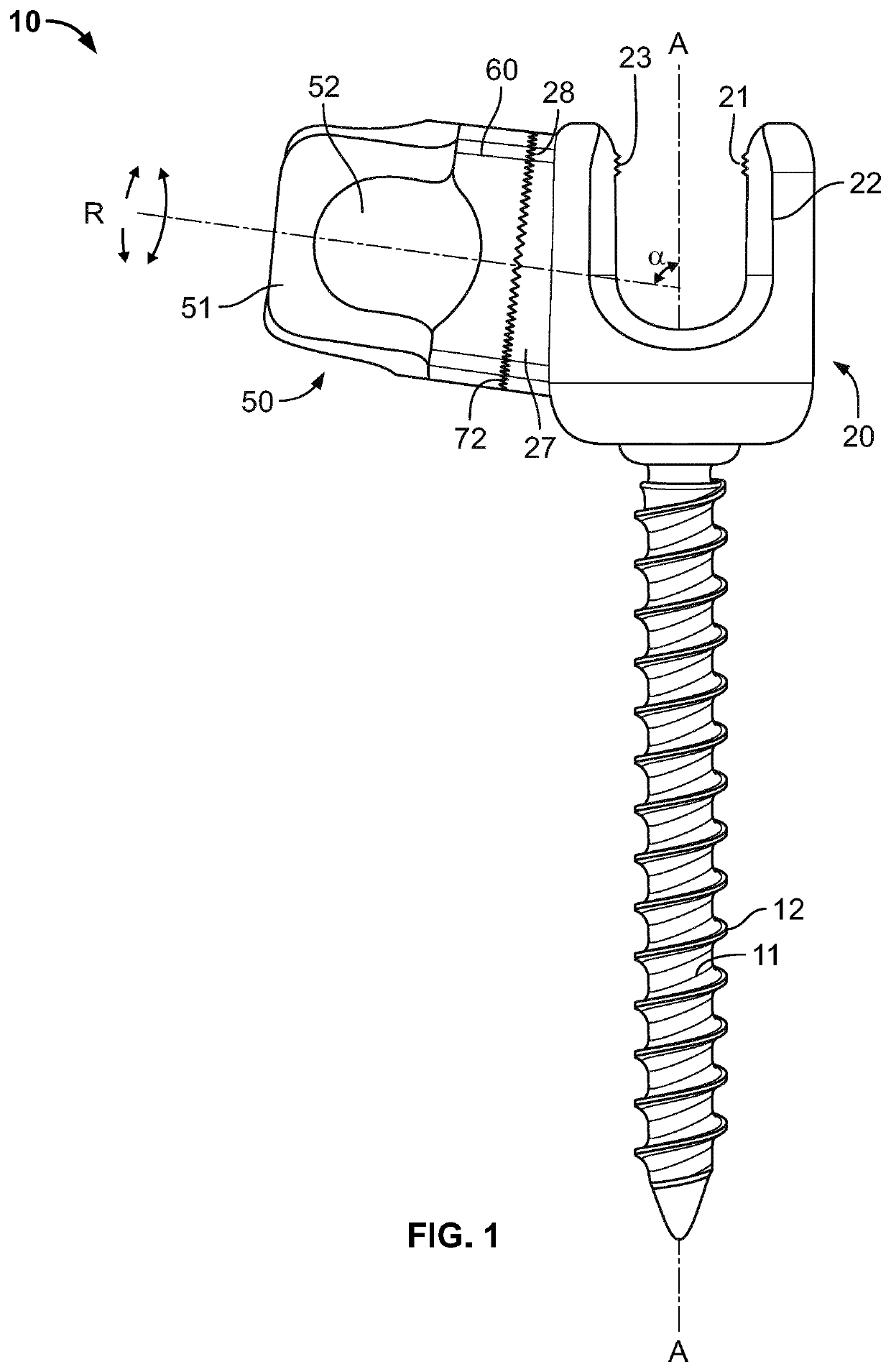
[0023]Referring now in detail to the drawings, FIG. 1 shows the pedicle screw 10 according to the invention. Pedicle screw 10 consists of a shaft 11 having helical threads 12 for attaching to bone, a first rod coupling head 20 and a second rod coupling head 50. First rod coupling head 20 is in the form of an open connector, with side walls 22, a cavity 21 for receiving a rod, and threads 23 near a top section for receiving a set screw. Shaft 11 has a longitudinal axis A running through it. Connected to first rod coupling head 20 is a second rod coupling head 50, which is connected to a connector segment 27 of first rod coupling head 50 by a connector plate 60. Connector plate 60 is connected so as to be freely rotatable about an axis of rotation R relative to connector segment 27. Axis of rotation R is not perpendicular to longitudinal axis A, and instead is disposed at an angle α of approximately 83 degrees from axis A, or in a range of preferably 70-85 degrees from axis A. A C-sha...


PUM


Abstract

A spinal fixation device for securing two stabilizing rods to bone, such as the spine, pelvis or cranium, has a threaded shaft configured for fastening to bone, a first (primary) rod coupling head and a secondary rod coupling head. The threaded shaft has a longitudinal axis and the first rod coupling head is connected to the threaded shaft. The first rod coupling head has a side wall and a cavity for receiving a rod, the cavity being open toward a top of the first rod coupling head. In a neutral position of the first rod coupling head, the first rod coupling head extends symmetrically around the longitudinal axis of the threaded shaft. The second rod coupling head is rotatably connected to the first rod coupling head, around an axis of rotation. The axis of rotation is disposed at an angle that is not perpendicular to the longitudinal axis of the threaded shaft when the first rod coupling head is in the neutral position. This allows for two rods to be manipulated independently through different axis planes at any single point of bony fixation.

Description

BACKGROUND OF THE INVENTION1. Field of the Invention[0001]This invention relates to a spinal fixation device such as a pedicle screw, that is used in spinal surgery including cervical, thoracic, lumbar, pelvic and posterior cranial surgery. In particular, the invention relates to a fixation device (e.g., pedicle screw, lateral mass screw, pelvic bolt, cranial fixation device) having a primary rod-securing element that is rotatably connected to a second rod-securing element having an aperture, so that two rods can be mounted to a single device, and adjustments can be made to the position of the rods with respect to each other.[0002]This allows for the primary rod to be secured in the polyaxial plane, and secondary rod to be secured in the monoaxial plane. This arrangement allows for the highest degree of biomechanical stability, while affording the necessary level of patient safety and surgeon preference. The arrangement of the present invention allows for both primary and secondary ...

Claims


Application Information

Patent Timeline
25 Mar 2021
Publication
US20210085372A1
IPC
A61B17/70
CPC
A61B17/7034; A61B17/7037; A61B17/7038; A61B17/7001; A61B17/7052; A61B17/7049
Inventors
KOUTSOUMBELIS, STELIOS