Multipoint angled fixation implants for multiple screws and related methods

a multi-angle fixation and screw technology, applied in the field of bone anchor assemblies, can solve the problems of less reliable and/or inconsistent tightening of the wing, difficulty in making certain bone anchor placements with angular trajectories, and difficulty in locating the distal portion of the wing in close proximity to the bone to facilitate proper engagemen

Active Publication Date: 2021-03-25
MEDOS INT SARL
View PDF0 Cites 4 Cited by
  • Summary
  • Abstract
  • Description
  • Claims
  • Application Information

AI Technical Summary

Benefits of technology

[0012]In another aspect, a method of securing a primary bone anchor assembly to bone is provided, the method can include driving a primary bone anchor having a receiver member coupled to a proximal end of the bone anchor into a vertebral level in a spine of a patient, positioning a rod in the receiver member, attaching a closure mechanism to the receiver member to retain the rod in the receiver member, coupling a proximal portion of a wing to at least one of the closure mechanism and the receiver member. The wing can have a distal portion defining a first auxiliary bone anchor opening and a second auxiliary bone anchor opening and a spanning portion connecting the proximal portion and the distal portion, where each of the first auxiliary bone anchor opening and the second auxiliary bone anchor opening extend at an oblique angle relative to a proximal-distal axis of the spanning portion. The method can include positioning the wing in one of a first position in which a first auxiliary bone anchor and a second auxiliary bone anchor received within the wing conform to the vertebral level into which the bone anchor is driven and a second position in which at least one of a first auxiliary bone anchor and a second auxiliary bone anchor received within the wing extends across a facet plane of the vertebral level into which the bone anchor is driven, inserting a first auxiliary bone anchor through the first bone anchor opening at a first trajectory, inserting a second auxiliary bone anchor through the second bone anchor opening at a second trajectory, and driving the first auxiliary bone anchor at the first trajectory into the vertebral level and the second auxiliary bone anchor at the second trajectory into the bone such that the first auxiliary bone anchor and the second auxiliary bone anchor augment fixation of the primary bone anchor.

Problems solved by technology

This can be undesirable, especially in the cervical region of the spine where there is limited bone area in which to install additional bone anchors.
In some instances, however, a surgeon may experience difficulty in making certain bone anchor placements having angular trajectories.
Variability in the bony anatomy of the spine can make it difficult to position the distal portion of the wing in close proximity to bone to facilitate proper engagement or purchase with the anchor.
This can cause less reliable and / or inconsistent tightening of the wing 530 to the bone anchor assembly 500.
In some instances, however, a surgeon may experience difficulty in making certain bone anchor placements having angular trajectories.
Variability in the bony anatomy of the spine can make it difficult to position the distal portion of the wing in close proximity to bone to facilitate proper engagement or purchase with the anchor.
With respect to the embodiments of FIGS. 3A-6E, in some applications an angled distal portion of a wing could interfere with the bony anatomy of the spine or limit optimal placement of an auxiliary bone anchor screw.

Method used


Image

  • Multipoint angled fixation implants for multiple screws and related methods
  • Multipoint angled fixation implants for multiple screws and related methods
  • Multipoint angled fixation implants for multiple screws and related methods

Examples


Embodiment Construction

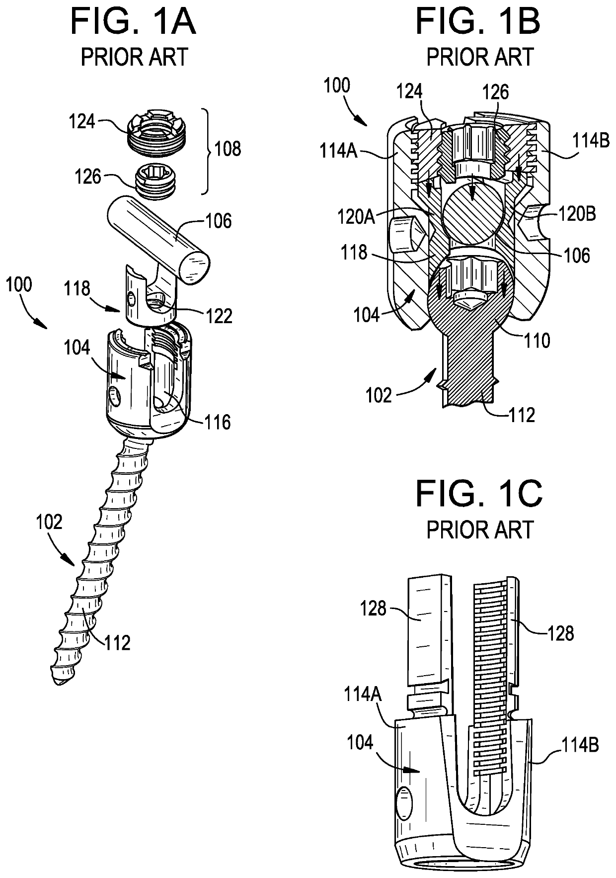
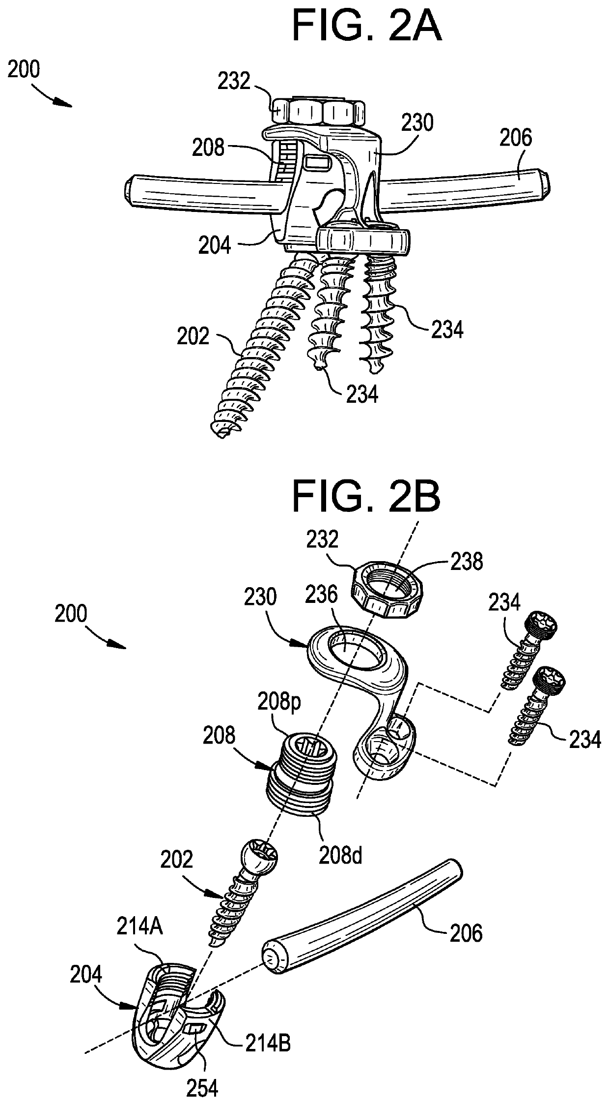
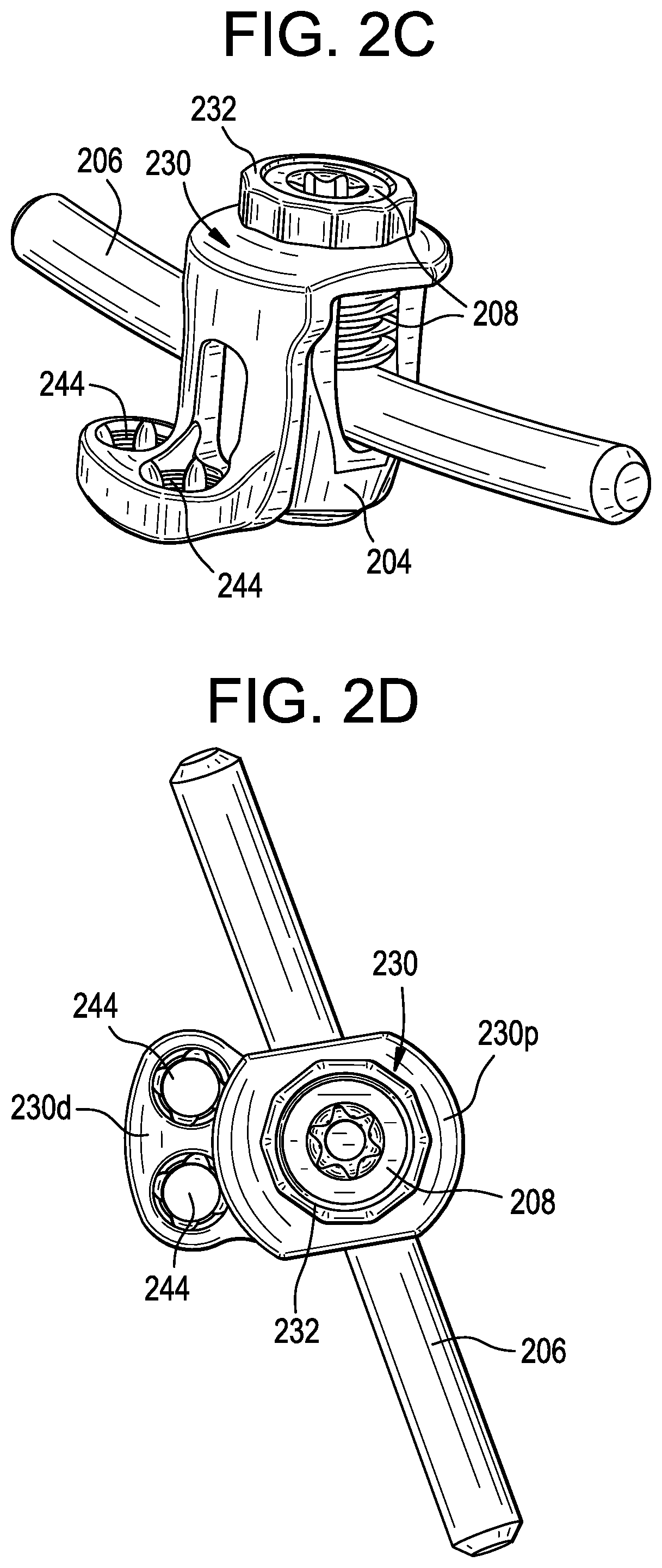
[0078]Bone anchor assemblies are disclosed herein that can provide for improved fixation as compared with traditional bone anchor assemblies. An exemplary assembly can include a bracket or wing that extends down from the receiver member and accommodates one or more auxiliary bone anchors that augment the fixation of the assembly's primary bone anchor. Another exemplary assembly can include a plate that is seated between the receiver member and the rod and accommodates one or more auxiliary bone anchors that augment the fixation of the assembly's primary bone anchor. Another exemplary assembly can include a hook that extends out from the receiver member to hook onto an anatomical structure or another implant to augment the fixation of the assembly's primary bone anchor. Surgical methods using the bone anchor assemblies described herein are also disclosed.

[0079]Certain exemplary embodiments will now be described to provide an overall understanding of the principles of the structure, f...


PUM


Abstract

Bone anchor assemblies and related methods are disclosed herein that can provide for improved fixation of a primary bone anchor. A bone anchor assembly can include a wing with a distal portion that can define a plurality of auxiliary bone anchor openings. Each auxiliary bone anchor opening can receive an auxiliary bone anchor that can augment fixation of a primary bone anchor of the bone anchor assembly. The plurality of auxiliary bone anchor openings can be oriented such that, when the wing is coupled to a primary bone anchor assembly of a vertebral level in a first configuration, at least one auxiliary bone anchor can be driven to extend across a facet plane of the vertebral level and, when coupled in a second configuration, each auxiliary bone anchor received within the wing can be driven to conform to the vertebral level.

Description

FIELD[0001]Orthopedic implants and related methods are disclosed herein. For example, bone anchor assemblies with multiple bone engagement points are disclosed.BACKGROUND[0002]Bone anchor assemblies can be used in orthopedic surgery to fix bone during healing, fusion, or other processes. In spinal surgery, for example, bone anchor assemblies can be used to secure a spinal fixation element to one or more vertebrae to rigidly or dynamically stabilize the spine. Bone anchor assemblies can also be used as an engagement point for manipulating bone (e.g., distracting, compressing, or rotating one vertebra with respect to another vertebra, reducing fractures in a long bone, and so forth).[0003]The integrity with which the bone anchor assembly engages the bone can affect the transfer of corrective biomechanical forces. While a great amount of care is exercised when placing bone anchor assemblies, it is common that a bone anchor assembly will be inserted in a compromised state. For example, ...

Claims


Application Information

Patent Timeline
Patent Type & Authority Applications(United States)
IPC IPC(8): A61B17/70
CPCA61B17/7043A61B17/7002A61B17/7035A61B2017/564A61B17/7044A61B17/7067A61B17/7058A61B17/7041A61B17/7059A61B17/7032A61B17/8057
Inventor LEE, KEVINRAMSAY, CHRISTOPHERHAWKINS, J. RILEYMONTELLO, ALBERT
Owner MEDOS INT SARL
Why Eureka
Try Eureka