Portable thermal therapy and support apparatus for emergency medical treatment

a technology for medical treatment and support equipment, applied in the field of emergency medical treatment, can solve the problems of inconvenient use, large and heavy current devices, and inability to carry or use in a portable fashion at or near the point of injury,

Active Publication Date: 2021-03-25
RAND DAVID
View PDF0 Cites 3 Cited by
  • Summary
  • Abstract
  • Description
  • Claims
  • Application Information

AI Technical Summary

Benefits of technology

[0006]Upon operation of the gas valve, pressurized gas will flow into the gas chamber and the gas in the gas chamber will apply pressure to the liquid chamber and force the second thermal reaction component through the valve and into the fluid conduits and thereby into the thermal reaction compartments. The at least two thermal reaction components will react and transfer heat with the heat transfer surface, and the presence of the gas within the gas chamber will support and cushion the patient.
[0013]The method can include the step of operating the gas valve to place the thermal reaction components into contact with each other. Upon operation of the gas valve, pressurized gas will flow into the gas chamber and the gas in the gas chamber will apply pressure to the liquid chamber and force the second thermal reaction component through the check valve and into the fluid conduits and thereby into the reaction compartments. The at least two thermal reaction components will react and transfer heat between the thermal reaction compartments and the heat transfer surface. The presence of the gas within the gas chamber will cushion the surface portion of the patient.

Problems solved by technology

A significant issue in any portable apparatus is weight and size.
This is especially an issue with current therapeutic hypothermia devices.
Current devices are far too large and heavy to be used in a portable fashion at or nearest the point of injury.
Previously suggested more portable methods of therapeutic hypothermia have been found to be either too invasive or were found to produce unwanted serious complications.
Therefore, currently there is commonly a significant delay in initiating therapeutic hypothermia until a patient is transferred to a specialized unit in the hospital, which can be several hours after the initial injury.
By this time, much irreversible damage has already occurred.

Method used


Image

  • Portable thermal therapy and support apparatus for emergency medical treatment
  • Portable thermal therapy and support apparatus for emergency medical treatment
  • Portable thermal therapy and support apparatus for emergency medical treatment

Examples


Embodiment Construction

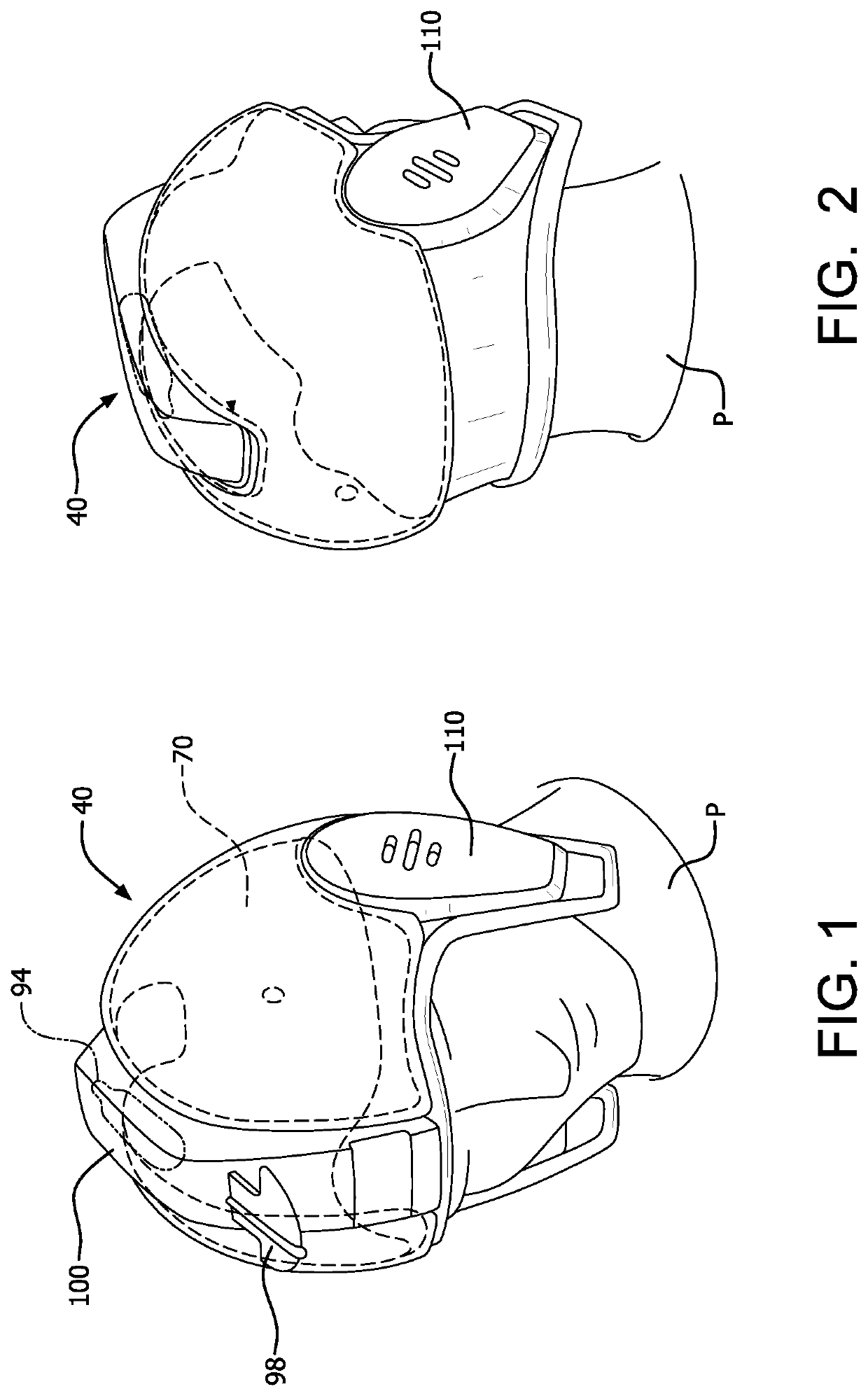
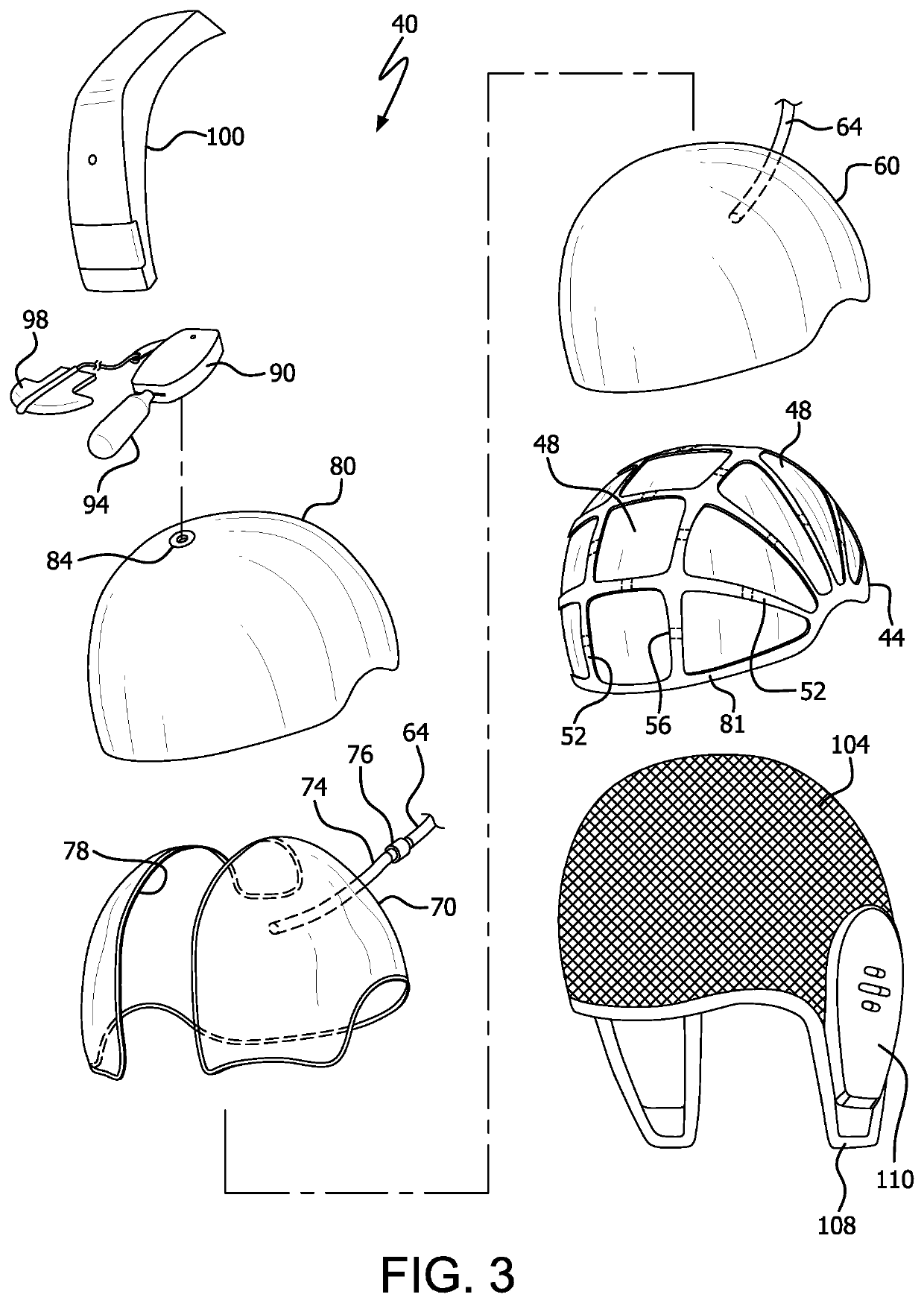
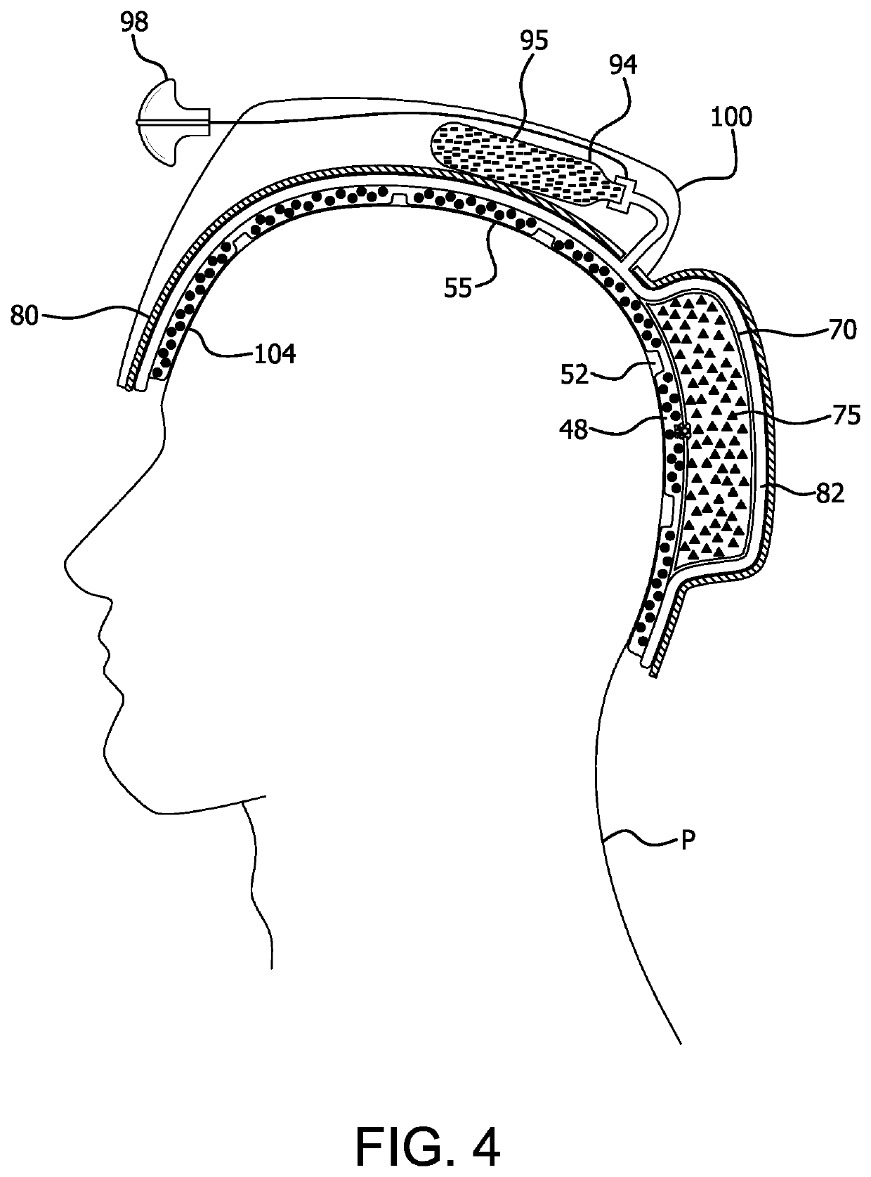
[0046]Thermal therapy apparatus according to the invention can include a flexible base for conforming to a portion of the patient. The base can be in the form of a headgear for a patient, comprising a flexible headpiece conforming to the head of the patient for engaging the head of the patient. A plurality of thermal reaction compartments can be provided, each compartment containing a first of at least two endothermic reaction components. The reaction compartments can be interconnected by fluid conduits. Each reaction compartment can be in thermal contact with a heat transfer surface for contacting the surface portion of the patient which will transfer heat with the head or corresponding body part of the patient. The thermal reaction components have an initial state where the thermal reaction components are separated from contact with each other, and a treatment state in which the thermal reaction components are placed into contact, wherein an endothermic or exothermic reaction take...


PUM


Abstract

A thermal therapy headgear for a patient includes a plurality of thermal reaction compartments, a liquid chamber, a gas chamber, and a gas container. The thermal reaction compartments contain a first of at least two thermal reaction components, and the liquid chamber contains the second thermal reaction component. The gas container has therein a pressurized gas and a gas valve for selectively releasing the pressurized gas into the gas chamber. The gas in the gas chamber will apply pressure to the liquid chamber and force the second thermal reaction component through the valve and into the thermal reaction compartments to react and transfer heat with the patient, and the presence of the gas within the gas chamber will cushion the patient. A method for conducting hypothermic therapy is also disclosed.

Description

FIELD OF THE INVENTION[0001]The present invention relates to the field of emergency medical treatment. More specifically the present invention relates to an emergency medical device for delivering thermal therapy and also support and cushioning to a patient as an emergency medical treatment.BACKGROUND OF THE INVENTION[0002]In recent years medical personnel have recognized in various emergency medical scenarios that irreparable damage to tissues of the brain and brainstem following oxygen deprivation, such as from cardiac arrest, stroke, or near-drowning, or alternatively from direct trauma, can be prevented and / or mitigated through rapid temperature reduction, known as therapeutic hypothermia or targeted temperature management. In other emergency medical scenarios, the application of heat is prescribed. Additionally, in numerous emergency medical scenarios proper positioning of the head of the patient is also of concern to open the airway of the patient for breathing and for optimal...

Claims


Application Information

Patent Timeline
Patent Type & Authority Applications(United States)
IPC IPC(8): A61F7/10A42B1/00
CPCA61F7/106A61F2007/0056A42B1/008A61F2007/0002A61F2007/0092A61F2007/0273A61F2007/0282A61F2007/0268A61F2007/0007A61F2007/0012A61F2007/0057A61F2007/0096
Inventor RAND, DAVIDRAND, WILLIAMECHEVERRI, FELIPE
Owner RAND DAVID
Why Eureka
Try Eureka