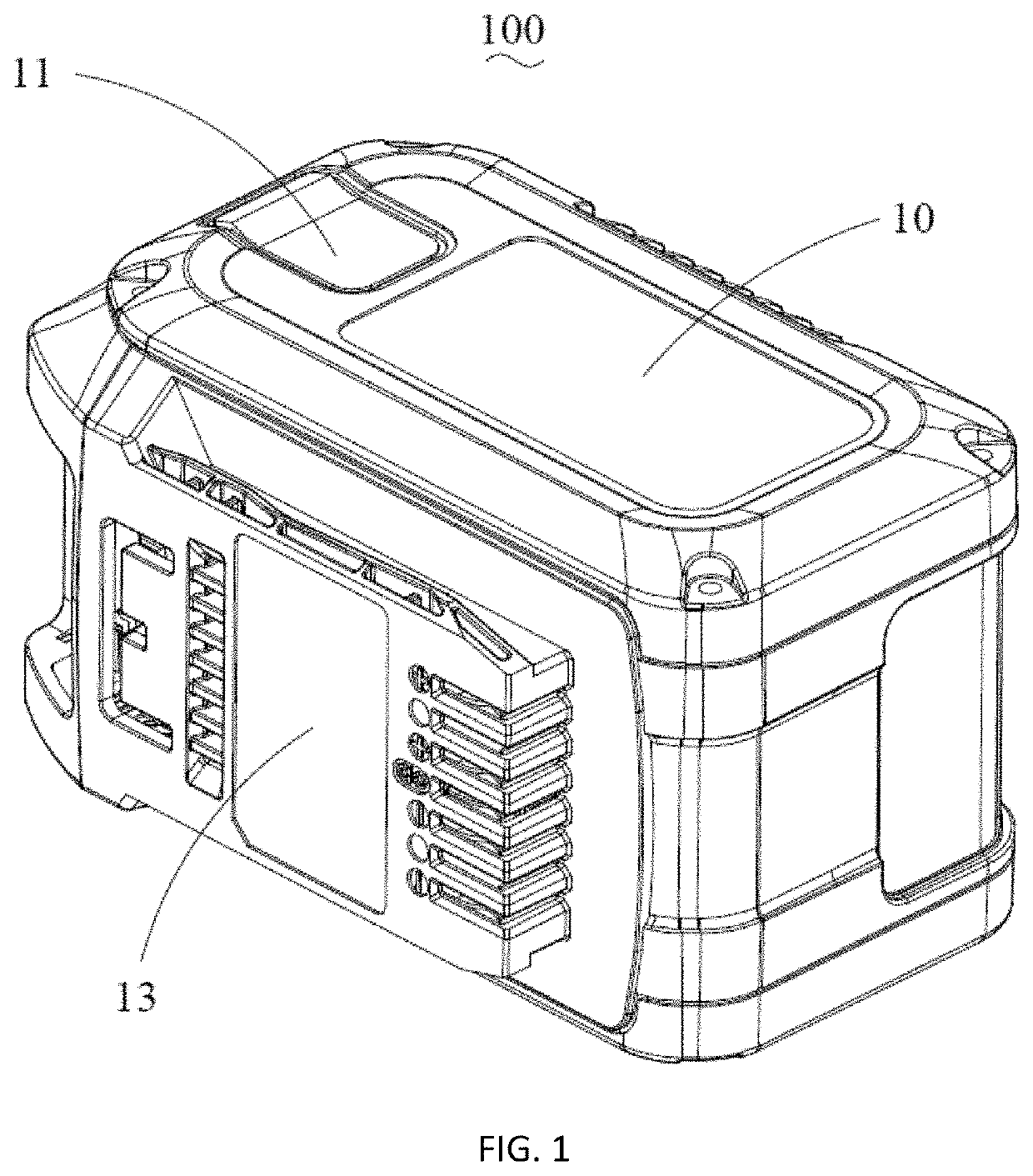
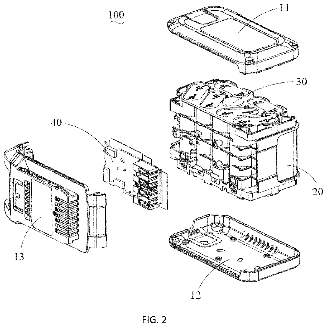
Battery pack

a battery pack and battery cell technology, applied in the field of batteries, can solve the problems of reducing user experience and affecting the normal use of batteries, and achieve the effects of extending the working time reducing the temperature of each area and facilitating the heat dissipation of the battery cell assembly

Pending Publication Date: 2021-03-25
GLOBE (JIANGSU) CO LTD
View PDF2 Cites 0 Cited by
  • Summary
  • Abstract
  • Description
  • Claims
  • Application Information

AI Technical Summary

Benefits of technology

[0006]The object of the present invention is to provide a battery pack, which assists the heat dissipation of the battery cell assembly through a heat dissipation assembly, which not only can make the temperature of each area of the battery cell assembly more balanced, but also effectively extend the working time of the battery cell assembly and reduce the decay rate of the battery cell assembly, thereby effectively extending the service life of the battery pack.
[0024]The beneficial effect of the present invention is that the battery pack of the present invention assists the heat dissipation of the battery cell assembly through the heat dissipation assembly, which can not only make the temperature of each area of the battery cell assembly more balanced, but also effectively extend the working time of the battery cell assembly and reduce the decay rate of the battery cell assembly, thereby effectively prolonging the service life of the battery pack.

Problems solved by technology

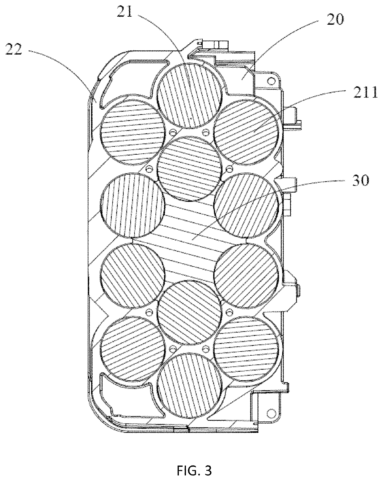
The battery cell located at the edge of the array dissipates heat quickly, while the battery cell located at the center of the array dissipates heat slowly, or even fails to dissipate heat effectively, so that the battery cell at the center of the battery cell assembly reaches the temperature value of the thermal protection for the battery cell fastest, which triggers the protection mechanism of the battery pack, the circuit board controls the battery pack to stop discharging, thereby affecting the normal use of the battery pack and reducing the user experience.

Method used


Image

  • Battery pack
  • Battery pack
  • Battery pack

Examples


second embodiment

[0043]FIG. 8 shows a heat dissipation assembly 50 according to a The heat dissipation assembly 50 includes a heat-absorbing member 51 and a heat-conducting member 52 in contact with the heat-absorbing member 51. The structure of the heat-absorbing member 51 is substantially the same as that of the heat-absorbing member 31. The heat-conducting member 52 includes a first heat-conducting member 521 and a second heat-conducting member 522. One end of the first heat-conducting member 521 is fixed on the top wall 11, and the other end is inserted into the heat-absorbing member 51. One end of the second heat-conducting member 522 is fixed on the bottom wall 12, and the other end is inserted into the heat-absorbing member 51. In this embodiment, the heat-conducting member 52 is a split type, but it can be understood that in other embodiments, the first heat-conducting member 521 and the second heat-conducting member 522 may form a whole, and one end is fixed to the top wall 11 or the botto...

third embodiment

[0044]FIG. 9 shows a heat dissipation assembly 60 according to a The structure of the heat dissipation assembly 60 is substantially the same as that of the heat dissipation assembly 50. The heat dissipation assembly 60 includes a heat-absorbing member 61 and a heat-conducting member 62 in contact with the heat-absorbing member 61. The difference is that the heat-conducting member 62 is a heat conducting sheet, that is, the heat-conducting member 62 includes a first heat-conducting sheet and a second heat-conducting sheet, the first heat-conducting sheet and the second heat-conducting sheet are substantially the same as the first heat-conducting member 521 and the second heat-conducting member 522. In this embodiment, one end of the heat-conducting member 62 is inserted into the heat-absorbing member 61, but it can be understood that in other embodiments, the heat-conducting member 62 further includes a heat conductor penetrates the heat-absorbing member 31 along the axial direction...

fourth embodiment

[0045]FIG. 10 shows a heat dissipation assembly 70 according to a The heat dissipation assembly 70 includes a heat-absorbing member 71 and a heat-conducting member 72 in contact with the heat-absorbing member 71. The heat-absorbing member 71 has the same structure as the heat-absorbing member 31, and a receiving cavity 711 is provided therein. The heat-conducting member 72 includes a hollow cylinder 721 and a plurality of heat dissipation fins 722. The cylinder 721 is disposed in the receiving cavity 711 and abuts against the side wall of the receiving cavity 711. The cylinder 721 is provided with a receiving groove 7211, in this embodiment, the hollow part of the cylinder forms the receiving groove 7211. One end of the heat dissipation fin 722 is installed on the sidewall of the receiving groove 7211, and the other end extends into the receiving groove 7211. It can be understood that, in other embodiments, the heat-conducting member 72 may not have the cylinder 721, and the heat d...


PUM

PropertyMeasurementUnit
heat-aaaaaaaaaa
heat-conductingaaaaaaaaaa
temperatureaaaaaaaaaa

Abstract

The invention provides a battery pack comprising a battery cell assembly and a heat dissipation assembly. The battery cell assembly comprises a battery cell array and a channel arranged in the battery cell array. The battery cell array is formed by arranging a plurality of cells in a certain form. The channel is enclosed by N cells, wherein N>2. The heat dissipation assembly comprises a heat-absorbing member arranged in the channel. The heat-absorbing member comprises N side walls, wherein the N side walls respectively abut against the side walls of the N battery cells. Compared with the prior art, the battery pack has the advantages that the battery pack assists the battery cell assembly in heat dissipation through the heat dissipation assembly, which can make the temperature of each area of the battery cell assembly more balanced.

Description

TECHNICAL FIELD[0001]This invention is a US application which claims the priority of CN application Serial No. 201910899648.X, filed on Sep. 23, 2019, the disclosures of which are hereby incorporated by reference in their entirety.TECHNICAL FIELD[0002]The invention relates to a battery pack.BACKGROUND ART[0003]The battery pack generally includes a housing, a battery cell assembly disposed in the housing, and a circuit board for controlling the state of charging and discharging of the battery pack. During the use of the battery pack, the battery cell assembly continuously releases heat. When the temperature of the battery cell assembly reaches the temperature value of the thermal protection for the battery cell, the battery pack will stop discharging under the control of the circuit board.[0004]Current battery cell assembly are usually composed of a plurality of cells to form an array. The battery cell located at the edge of the array dissipates heat quickly, while the battery cell l...

Claims


Application Information

Patent Timeline
Patent Type & Authority Applications(United States)
IPC IPC(8): H01M10/613H01M2/10H01M10/653H01M10/6551H01M10/659H01M50/204H01M50/213
CPCH01M10/613H01M2/1077H01M2/105H01M10/6551H01M10/659H01M10/653H01M10/617H01M10/655H01M50/213Y02E60/10H01M10/6555H01M10/643
Inventor WEI, LV
Owner GLOBE (JIANGSU) CO LTD
Why Eureka
Try Eureka