Check patentability & draft patents in minutes with Patsnap Eureka AI!

Positional error prediction device, prediction model generation device, positional error prediction method, prediction model generation method, and program

a technology of positional error and prediction device, which is applied in the direction of measurement device, instrument, satellite radio beaconing, etc., can solve the problem of receiving device affecting positional errors

Active Publication Date: 2021-04-15
MITSUBISHI HEAVY IND MACHINERY SYST LTD
View PDF3 Cites 0 Cited by
  • Summary
  • Abstract
  • Description
  • Claims
  • Application Information

AI Technical Summary

Benefits of technology

The patent text describes a device and method for predicting positional errors in a navigation system. The device takes into account the influence of multipath interference, which refers to the interference caused by multiple signals reflecting off objects along the path to the destination. By predicting these errors, the device can improve the accuracy of navigation to its destination. The technical effect of the invention is better prediction of positional errors in navigation systems.

Problems solved by technology

The satellite positioning system obtains a distance (pseudo distance) between the receiver and each of the plurality of satellites, from the signal received by the receiver, and specifies the position of the receiver based on these pseudo distances, but various factors are known to cause positional errors.
For example, arrangements of respective satellites from which signals can be received by the receiver affect positional errors.

Method used


Image

  • Positional error prediction device, prediction model generation device, positional error prediction method, prediction model generation method, and program
  • Positional error prediction device, prediction model generation device, positional error prediction method, prediction model generation method, and program
  • Positional error prediction device, prediction model generation device, positional error prediction method, prediction model generation method, and program

Examples


first embodiment

[0048]Hereinafter, a positional error prediction device and a prediction model generation device according to a first embodiment of the present invention will be described with reference to FIGS. 1 to 8.

(Function Configuration)

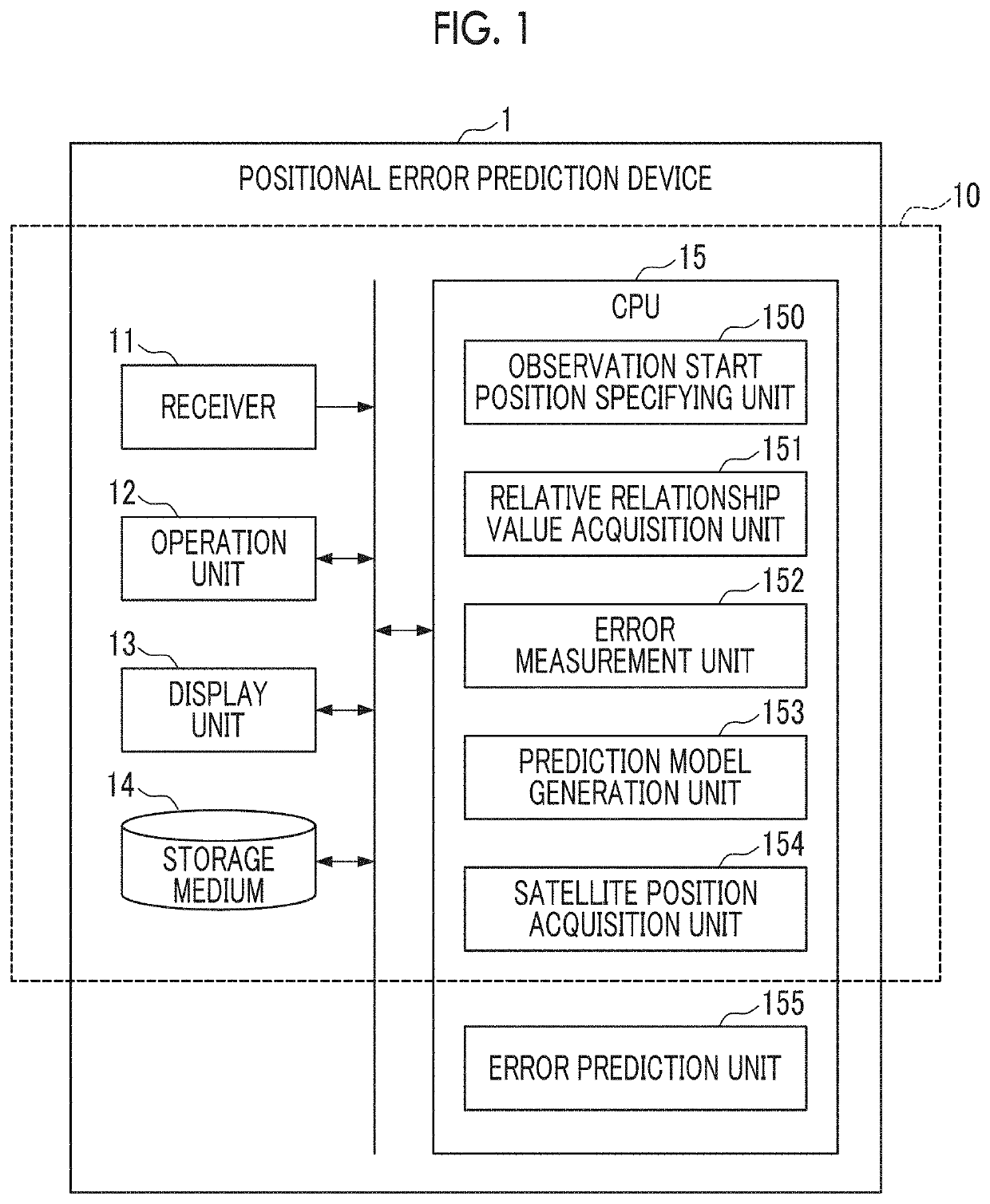
[0049]FIG. 1 is a diagram illustrating a functional configuration of a positional error prediction device and a prediction model generation device according to the first embodiment.

[0050]The positional error prediction device 1 according to the present embodiment is a device for predicting a positional error in a satellite positioning system. The positional error prediction device 1 is mounted on a vehicle (not illustrated) and predicts a positional error at a point where the vehicle is located.

[0051]In addition, in the following description, the point and the date and time in which the positional error prediction device 1 predicts the positional error are also referred to as “target point” and “target date and time”, respectively.

[0052]The positional error pr...

second embodiment

[0117]Next, a positional error prediction device 1 and a prediction model generation device 10 according to a second embodiment of the present invention will be described with reference to FIGS. 9 to 11.

[0118]Constituent elements common to those of the first embodiment are denoted by the same reference numerals, and a detailed description thereof is omitted.

(Function Configuration)

[0119]FIG. 9 is a diagram illustrating a functional configuration of a positional error prediction device and a prediction model generation device according to the second embodiment.

[0120]As illustrated in FIG. 9, the prediction model generation device 10 according to the present embodiment further includes a threshold setting unit 156.

[0121]The threshold setting unit 156 sets, as the distance threshold A, a distance at which the correlation function having a smallest residual variation is obtained, among the distances of the plurality of observable satellites from the observation start position L1.

(Proces...

third embodiment

[0139]Next, a positional error prediction device 1 and a prediction model generation device 10 according to a third embodiment of the present invention will be described with reference to FIG. 12.

[0140]The components common to those of the above-described respective embodiments are denoted by the same reference numerals, and a detailed description thereof is omitted.

[0141]In the present embodiment, the function of the threshold setting unit 156 of the prediction model generation device 10 is different from that of the second embodiment.

[0142]The threshold setting unit 156 according to the present embodiment measures a pseudo distance between the reference point and the observable satellite, and sets, as the distance threshold for each satellite, a distance from the observation start position L1 of the observable satellite to the position of the observable satellite when the pseudo distance has changed by a predetermined amount or more.

[0143]FIG. 12 is a diagram illustrating an examp...


PUM


Abstract

This positional error prediction device (1) is provided with: a satellite position acquisition unit (154) which acquires a receivable position of a satellite on a target date at a target time and a target point at which a positional error prediction is performed; a relative relationship value acquisition unit (151) which acquires a value of the relative relationship between the position of the satellite and an observation start position of the satellite at the target point; and an error prediction unit (155) which predicts, on the basis of the relative relationship value and a positional error prediction model generated in advance, a positional error on the target date at the target time and the target point.

Description

TECHNICAL FIELD[0001]The present invention relates to a positional error prediction device, a prediction model generation device, a positional error prediction method, a prediction model generation method, and a program.BACKGROUND ART[0002]In recent years, as a technique for specifying the position of a vehicle or the like, a satellite positioning system for specifying (positioning) the position of a receiver is widely used, by using a satellite that constitutes a Global Navigation Satellite System (GLASS) and a receiver that receives a signal from the satellite.[0003]The satellite positioning system obtains a distance (pseudo distance) between the receiver and each of the plurality of satellites, from the signal received by the receiver, and specifies the position of the receiver based on these pseudo distances, but various factors are known to cause positional errors. Predicting how much positional error will occur is important for improving positioning accuracy.[0004]For example,...

Claims


Application Information

Patent Timeline
Patent Type & Authority Applications(United States)
IPC IPC(8): G01S19/39G01S19/25G01S19/22G01S19/31G01S19/51
CPCG01S19/396G01S19/25G01S19/51G01S19/31G01S19/22G01S19/428G01S19/015
Inventor YAMADA, MASAHIROTAKAO, KENJIKORENAGA, TAKESHI
Owner MITSUBISHI HEAVY IND MACHINERY SYST LTD
Features
  • R&D
  • Intellectual Property
  • Life Sciences
  • Materials
  • Tech Scout
  • Unparalleled Data Quality
  • Higher Quality Content
  • 60% Fewer Hallucinations
Learn More