
Methods and devices for MEMS based particulate matter sensors

Pending Publication Date: 2021-04-29
SINGH NAVPREET +2
View PDF3 Cites 2 Cited by
  • Summary
  • Abstract
  • Description
  • Claims
  • Application Information

AI Technical Summary

Benefits of technology

This patent aims to improve particle detectors by using microelectromechanical systems (MEMS) resonators. The invention provides a method and device for detecting particles by exposing a MEMS resonator to a source of particles and monitoring a shift in the resonator's characteristic, such as its frequency or amplitude. The MEMS resonator is piezoelectrically driven, and a metal layer acts as the top electrode while the substrate acts as the bottom electrode. The invention allows for more accurate and efficient detection of particles, which can be useful in various fields such as manufacturing processes or environmental monitoring.

Problems solved by technology

These methods are expensive which, in conjunction with their size, limit their widespread usage.
These sensors make several assumptions to estimate the density and the size distribution of the particles, leading to inaccurate results.
As these sensors are based on sophisticated optical elements, they are also relatively expensive although smaller than the gravimetric based instruments.
Their cost and complicated use also mean that these are not generally deployed.
As such PM monitoring is not common within most environments the general population live and work in, being limited to national survey / monitoring or annual quality checks on air conditioning systems etc.
Although these implementations could help overcome the challenges of size and cost, they have failed to make it into commercial products due to issues related to not being able to clear the sensing elements from particles after each measurement, and the general lack of specific particle size distinction.

Method used


Image

  • Methods and devices for MEMS based particulate matter sensors
  • Methods and devices for MEMS based particulate matter sensors
  • Methods and devices for MEMS based particulate matter sensors

Examples


Embodiment Construction

[0039]The present description is directed to microelectromechanical systems (MEMS) resonators and more particularly to MEMS resonator devices for particle detector sensors.

[0040]The ensuing description provides representative embodiment(s) only, and is not intended to limit the scope, applicability, or configuration of the disclosure. Rather, the ensuing description of the embodiment(s) will provide those skilled in the art with an enabling description for implementing an embodiment or embodiments of the invention. It being understood that various changes can be made in the function and arrangement of elements without departing from the spirit and scope as set forth in the appended claims. Accordingly, an embodiment is an example or implementation of the inventions and not the sole implementation. Various appearances of “one embodiment,”“an embodiment” or “some embodiments” do not necessarily all refer to the same embodiments. Although various features of the invention may be descri...


PUM


Abstract

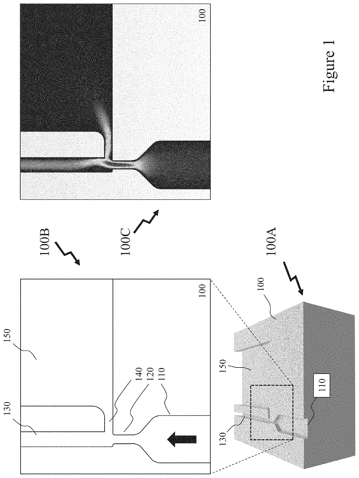
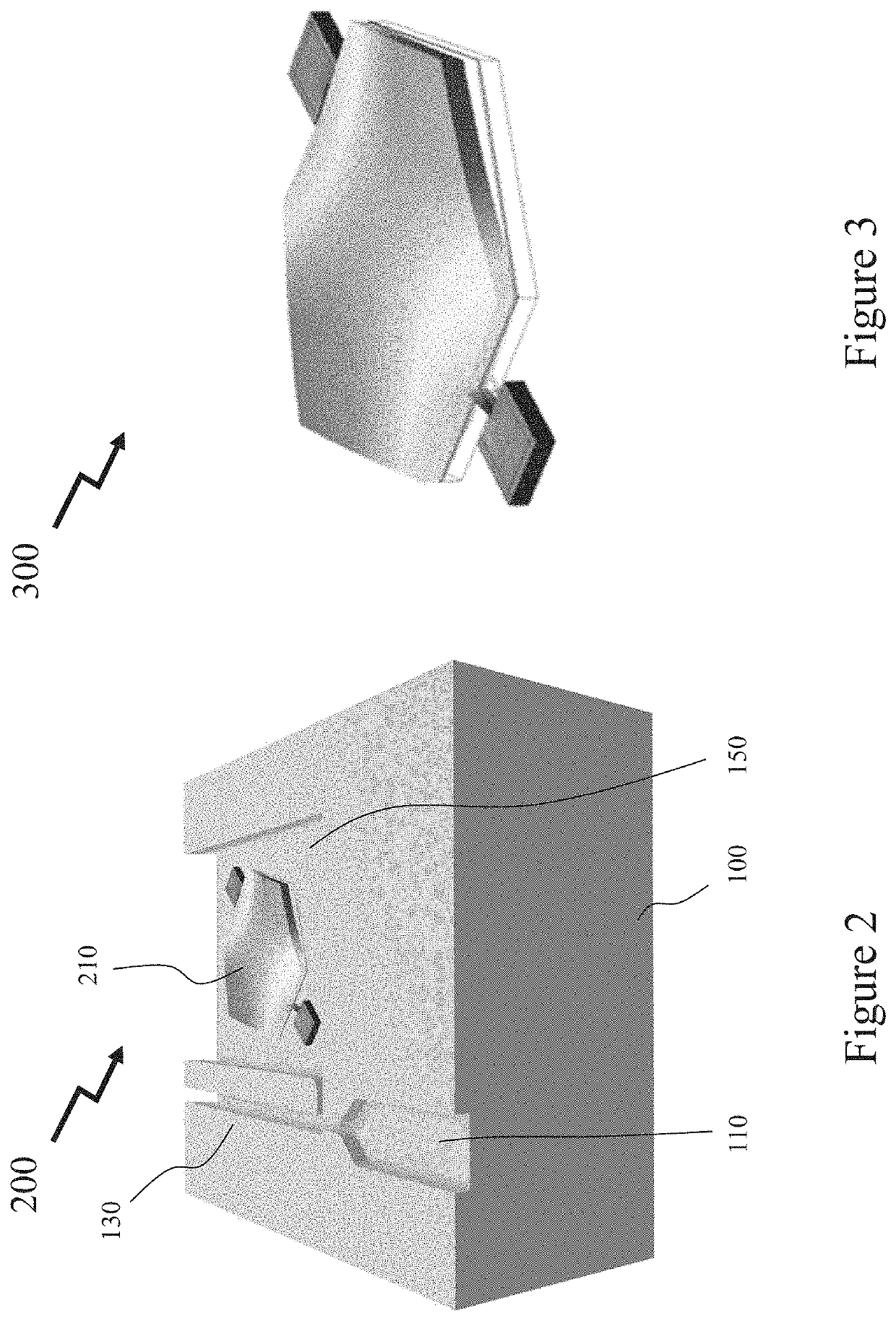
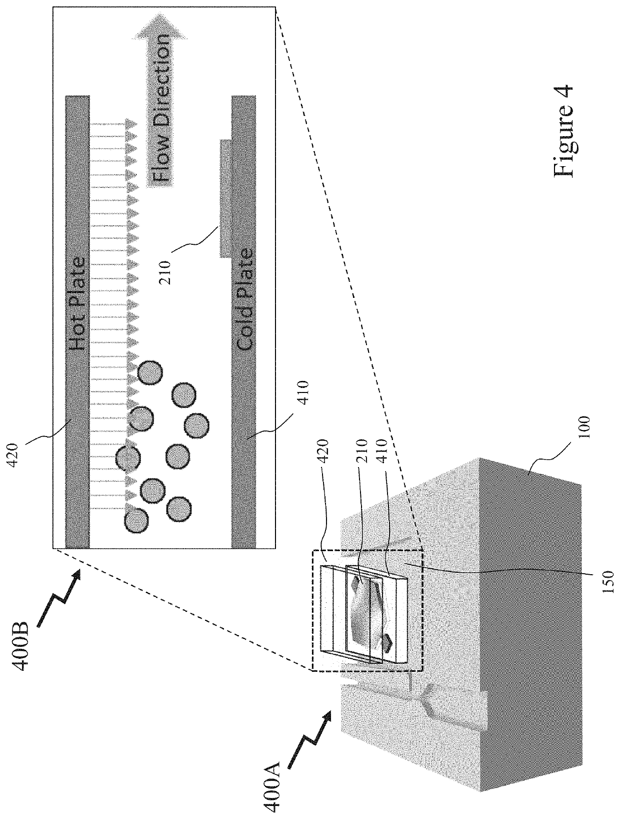
Airborne pollutants from natural and man-made sources are an increasing where their aerodynamic properties determine how far into the human respiratory system they penetrate. International and national guidelines or regulatory limits specify limits for particulate matter (PM) at different particulate dimensions leading to a requirement for low cost compact PM detectors / sensors. A flow of known and desired size particles are separated and guided by a virtual impactor towards a microelectromechanical systems (MEMS) sensor, e.g. MEMS resonator, yielding the required PM detectors / sensors. Further, in conjunction with the virtual impactor and MEMS sensor additional elements are provided to exploit thermophoresis or di-electrophoresis such that the particles within the sensing area of the MEMS sensor can be removed. Accordingly, the MEMS sensor based particle detector / sensor can be periodically reset allowing for extended operational life of the MEMS sensor based particle detector / sensor and / or enhanced performance over extended periods.

Description

CROSS-REFERENCE TO RELATED APPLICATIONS[0001]This patent application claims the benefit of priority from U.S. Provisional patent application 62 / 926,668 filed Oct. 28, 2019 entitled “Methods and Devices for MEMS based Particulate Matter Sensors”, the entire contents of which are incorporated herein by reference.FIELD OF THE INVENTION[0002]This patent application relates to microelectromechanical systems (MEMS) and more particularly to MEMS devices for particle detector sensors.BACKGROUND OF THE INVENTION[0003]The increase in the amount of airborne pollutants is a rising concern in developed as well as developing countries. These airborne particles consist of natural and man-made sources. Their aerodynamic properties determine how far they can get into the human respiratory system. The World Health Organization (WHO) sets limits on the amount of particulate matter (PM) that a human body can tolerate without risking respiratory or cardiovascular diseases. This limit is 10 μg / m3 annual ...

Claims


Application Information

Patent Timeline
IPC IPC(8): G01N15/02H01L41/113H01L41/04
CPCG01N15/0255G01N2015/0261H01L41/04H01L41/1132G01N15/0606G01N2015/0046G01N2001/2223G01N1/2208G01H13/00G01H11/08G01N27/4163H10N30/80H10N30/302
Inventor SINGH, NAVPREETELSAYED, MOHANNADEL-GAMAL, MOURAD
Owner SINGH NAVPREET
Learn More