
Method & apparatus for controlling the motion of a robotic device

Inactive Publication Date: 2010-04-01
NORTH END TECH
View PDF14 Cites 17 Cited by
  • Summary
  • Abstract
  • Description
  • Claims
  • Application Information

AI Technical Summary

Benefits of technology

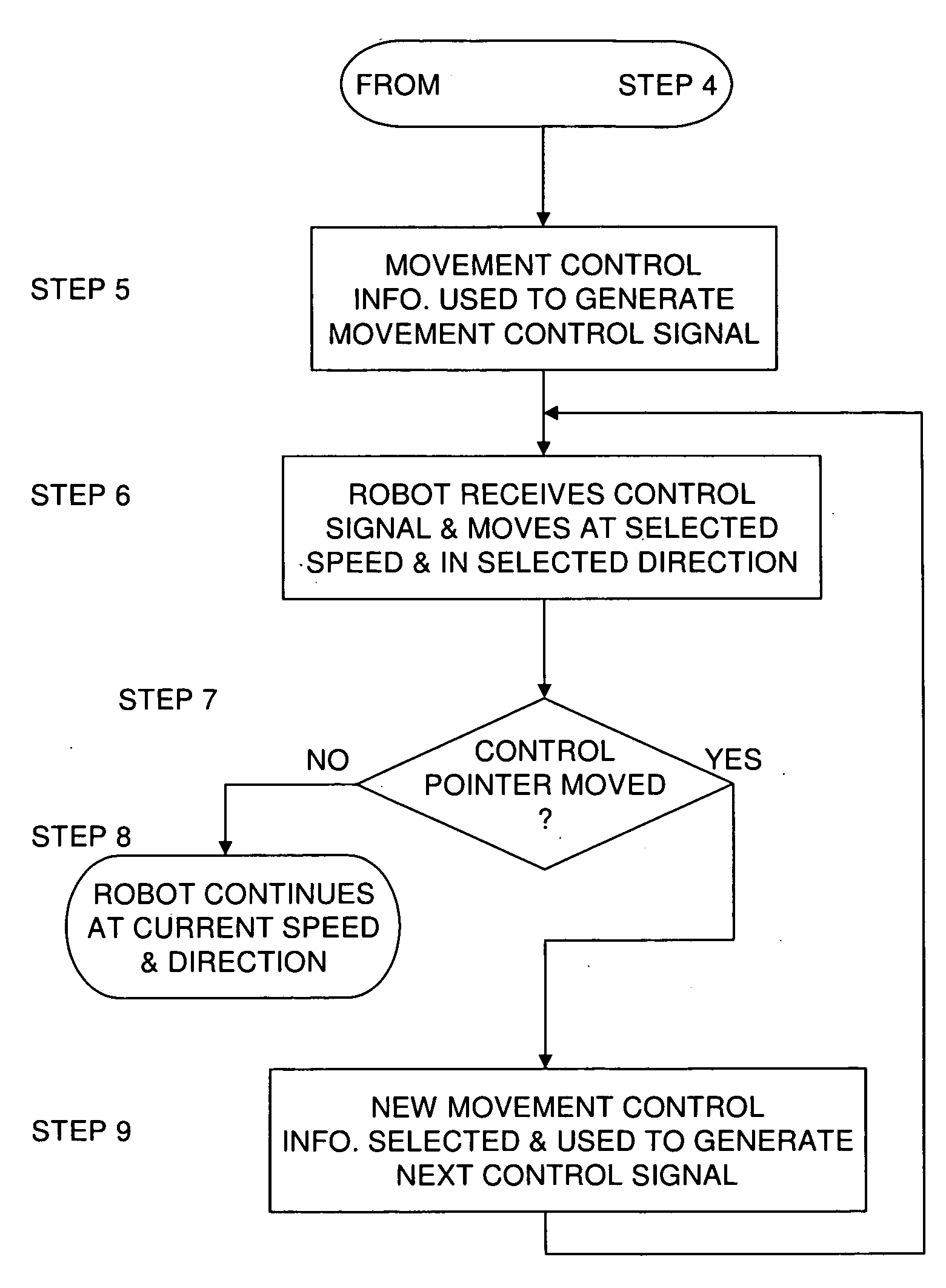
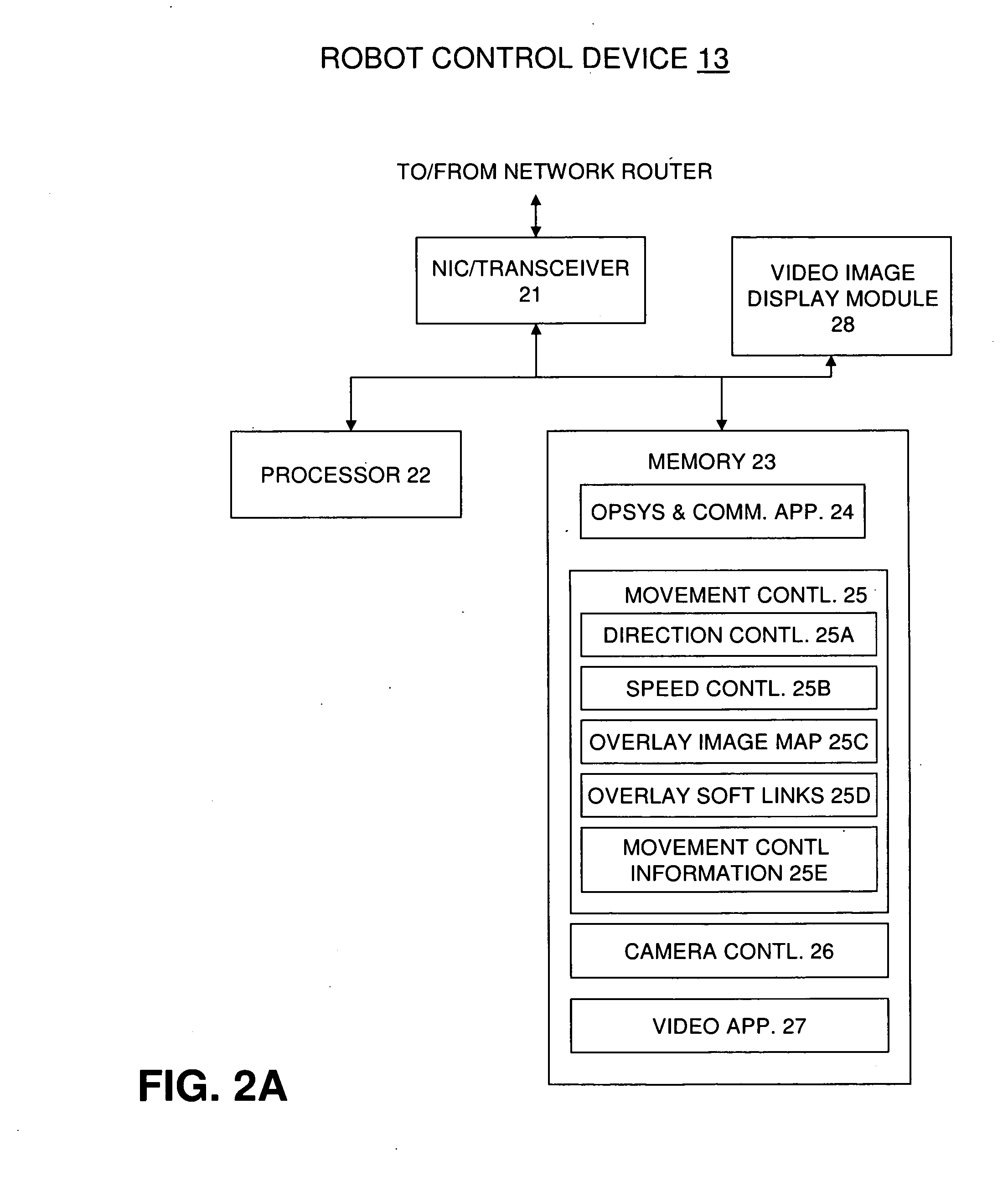
[0007]The limitations associated with the prior art robot movement control methods are mitigated by displaying a robot movement control overlay in the field of a real-time video image generated by a camera mounted on a robot. The method for controlling the movement of a robot is comprised of a robot movement control overlay that is displayed in the field of a real-time video image that is generated by a camera mounted on the robot; a location within the robot movement control overlay is selected that corresponds to the desired direction and speed of the robot movement; selection of this location within the overlay causes a control message to be generated and sent to the robot that includes the desired direction and speed information; the robot receives the control message and uses the direction and speed information contained in the message to move in the selected direction and at the selected speed.

Problems solved by technology

Although all of the robot movement control methods described above are effective means to control the movement of a robotic device in its environment, they are limited to either pre-selecting a position in space to command a robot to move to or they are limited to a real-time movement control icon that, although proximate to the representation of the robot's environment, forces the user to move the focus of their eyes back and forth from the movement control icon to the environmental representation to determine how and when to control a robots movements.
This continual visual refocusing from one position on a computer monitor screen used to control a robots movement to another position on the screen that displays the robots movement is a less than ideal method for controlling the movement of a robot.

Method used


Image

  • Method & apparatus for controlling the motion of a robotic device
  • Method & apparatus for controlling the motion of a robotic device
  • Method & apparatus for controlling the motion of a robotic device

Examples


Embodiment Construction

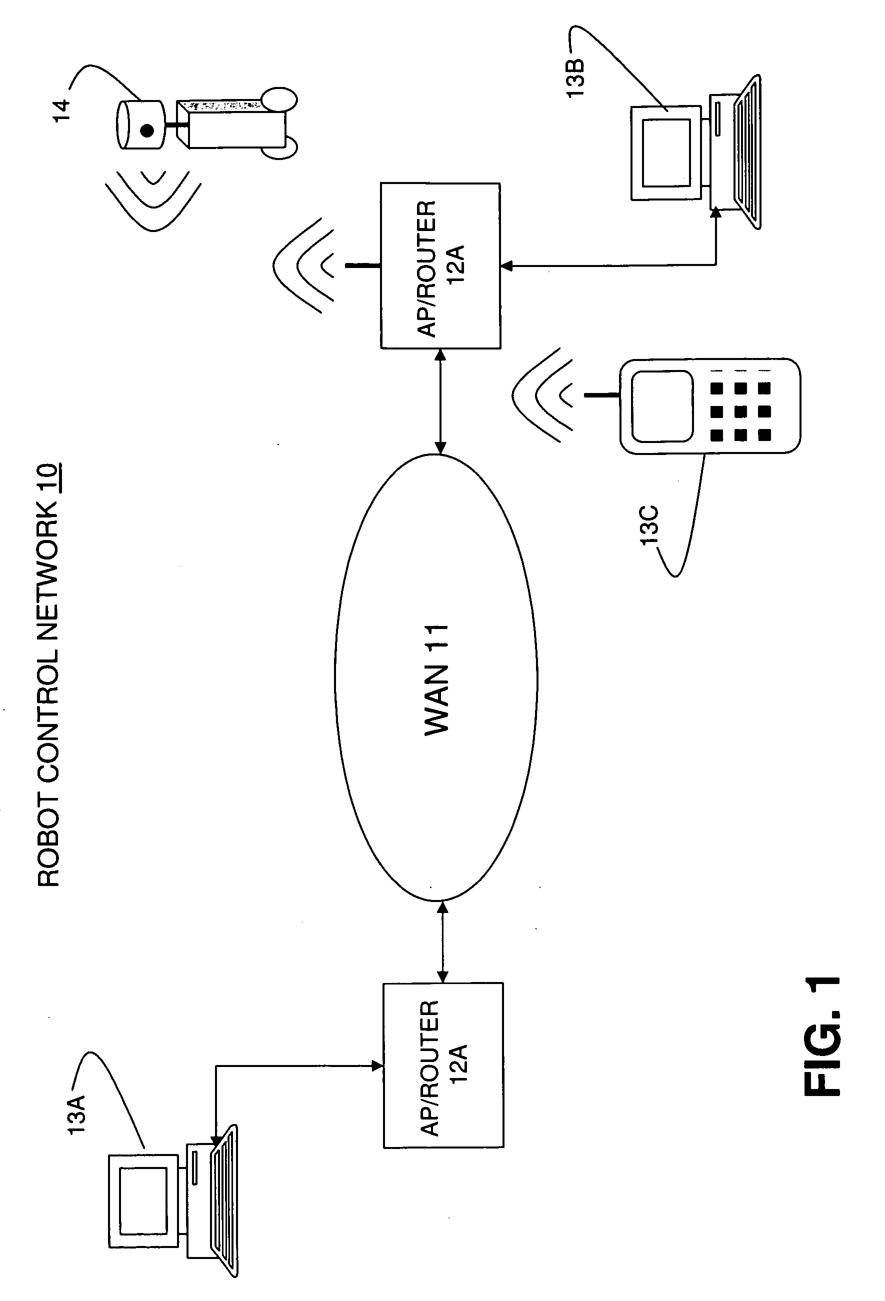
[0015]Typically, there are two classes of mobile robotic devices. One class of device can move around their environment autonomously and a second class of device can be commanded to move around their environment manually. Mobile robotic devices exist that combine both automatic movement and movement under manual control; however, this description is directed primarily too mobile robotic devices that are manually controlled to move around their environment. This manual control of a robotic device's movement can be performed in a location remote from the robotic device or it can be performed locally to the robotic device. FIG. 1 shows a robot control network 10 that includes a wide area network (WAN) 11, two routers or access points 12A and 12B, three robot control devices 13A, 13B and 13C and a mobile robotic device 14 which will be referred to simply here as a “robot”. The WAN 11 can be a public network such as the Internet or a private, enterprise network and it generally operates ...


PUM


Abstract

A robot movement control device is connected to a communications network in a remote location relative to a robotic device that is also connected to the communications network. The robot movement control device is an electronic device with a video display for displaying a real-time video image sent to it by a camera associated with the robot. A robot movement control overlay is displayed in the field of the real-time video image at the robot control device and robot control commands are generated by selecting locations within the boundary of the movement control overlay which include speed and directional information. The control commands are sent by the robot control device over the network to the robot which uses the commands to adjust its speed and direction of movement.

Description

FIELD OF THE INVENTION [0001]1. Field of the Invention[0002]The invention relates generally to the remote control of robotic device motion and specifically to a user interface that includes a movement control overlay function that is manipulated to control the motion of a robotic device.[0003]2. Background[0004]Mobile, electromechanical devices such as robotic devices are designed to move around their environment, whether this environment is inside a building or an outside environment. Some of these robotic devices are designed to move autonomously and some are designed to move according to user generated commands. Commands to control the movement of a robotic device can be generated by a user locally, with respect to the robotic device, such that the user is able to directly observe and then control the robotic devices movement with a wireless control module for instance, or commands to control the movement of a robotic device can be generated remotely by a user and sent over a net...

Claims


Application Information

Patent Timeline
IPC IPC(8): G05B15/00
CPCG05D1/0038
Inventor ROOT, TIMOTHY D.MULLER, JEFFREY T.
Owner NORTH END TECH
Learn More