LCDI Power Cord System and Method

a power cord and lcdi technology, applied in the field of power cords, can solve the problems of increased cost of power cords, leakage between phase lines, fire and property damage, etc., and achieve the effect of minimizing damage to inrush current and minimizing tim

Active Publication Date: 2021-04-29
TOWER MFG
View PDF0 Cites 5 Cited by
  • Summary
  • Abstract
  • Description
  • Claims
  • Application Information

AI Technical Summary

Benefits of technology

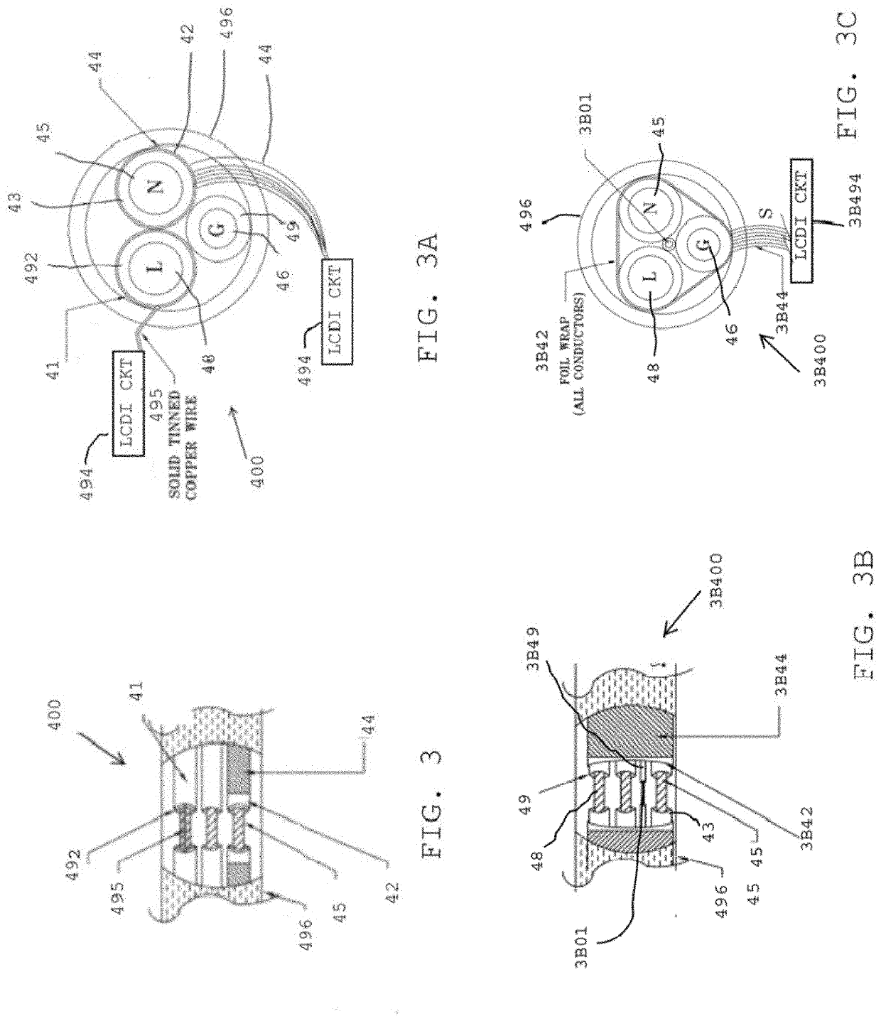
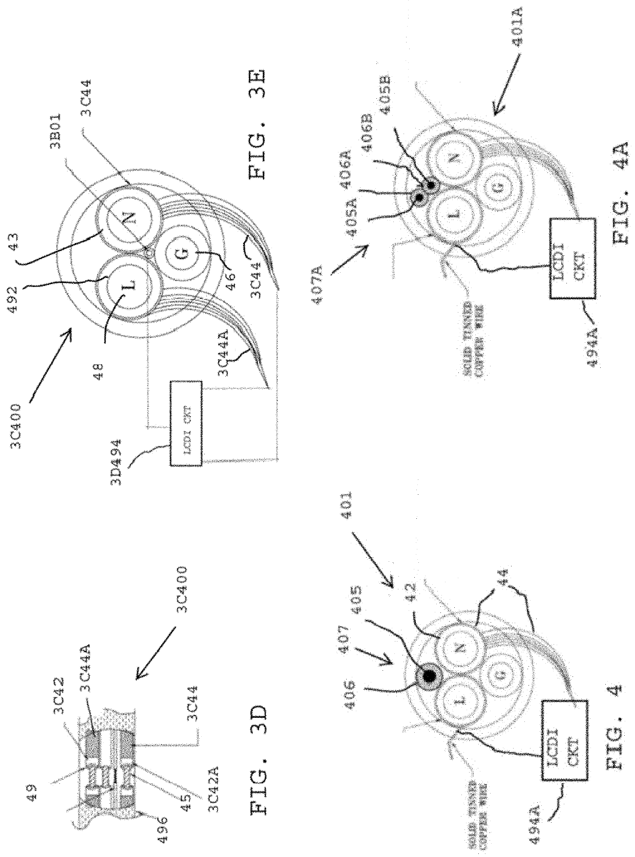
[0014]In accordance with another embodiment of the present invention a method for interrupting AC line voltage between an alternating current (AC) line end and a load end of a shielded power cord upon detection of a power cord fault is provided. The method includes providing a leakage current detection circuit (LCDC) for detecting AC leakage current from the power cord and interrupting line voltage between the AC line end and the load end of the shielded power cord if leakage current is detected. The method includes connecting the LCDC and SIC to the shielded power cord and providing a power supply circuit (PSC) for energizing the LCDC, SIC, and the shielded power cord with a voltage. Providing the LCDC further includes providing a bi-stable latching device having an on / off state and a charge holding device connected to a controlling port of the bi-stable latching device; such as, for example, a transistor base or an SCR gate port. The method includes, during normal operation, charging the charge holding device to a charge less than the trigger charge needed to trigger the bi-stable latching device to its on-state, but of sufficient charge to minimize the time needed to trigger the device if a fault is detected and to minimize damaging inrush current. The method further includes providing a shield integrity circuit (SIC) for monitoring shielded power cord integrity and interrupting line voltage between the AC line end and the load end of the shielded power cord if shield integrity is compromised.

Problems solved by technology

Such a power cord may age due to long-term use, or become damaged when the appliance is moved, which may cause a leakage between the phase line and the neutral or ground lines in the cord.
Such leakage current may cause sparks, which may cause fire and property damages.
The cost of the power cord has increased due to the increase cost of the copper material.

Method used


Image

  • LCDI Power Cord System and Method
  • LCDI Power Cord System and Method
  • LCDI Power Cord System and Method

Examples


Embodiment Construction

[0044]The following brief definition of terms shall apply throughout the application:

[0045]The term “comprising” means including but not limited to, and should be interpreted in the manner it is typically used in the patent context;

[0046]The phrases “in one embodiment,”“according to one embodiment,” and the like generally mean that the particular feature, structure, or characteristic following the phrase may be included in at least one embodiment of the present invention, and may be included in more than one embodiment of the present invention (importantly, such phrases do not necessarily refer to the same embodiment);

[0047]If the specification describes something as “exemplary” or an “example,” it should be understood that refers to a non-exclusive example; and

[0048]If the specification states a component or feature “may,”“can,”“could,”“should,”“preferably,”“possibly,”“typically,”“optionally,”“for example,” or “might” (or other such language) be included or have a characteristic, t...


PUM

PropertyMeasurementUnit
gate voltageaaaaaaaaaa
AC poweraaaaaaaaaa
voltageaaaaaaaaaa

Abstract

A system and method for an LCDI power cord and associated circuits is provided. The system and method include energizing shielded neutral wires and shielded line wires and monitoring the energized shields for surges, e.g., arcing, detected by a Leakage Current Detection Circuit (LCDC) and/or voltage drops, e.g., shield breaks, detected by a Shield Integrity Circuit (SIC).

Description

CROSS-REFERENCE TO RELATED APPLICATIONS[0001]The present continuation-in-part application is related to, claims the earliest available effective filing date(s) from (e.g., claims earliest available priority dates for other than provisional patent applications; claims benefits under 35 USC § 119(e) for provisional patent applications), and incorporates by reference in its entirety all subject matter of the following listed application(s) (the “Related Applications”) to the extent such subject matter is not inconsistent herewith; the present application also claims the earliest available effective filing date(s) from, and also incorporates by reference in its entirety all subject matter of any and all parent, grandparent, great-grandparent, etc. applications of the Related Application(s) to the extent such subject matter is not inconsistent herewith:[0002]U.S. provisional patent application 63 / 013,742, entitled “LCDI Shield Continuity Monitoring Circuits”, naming Victor V. Aromin as f...

Claims


Application Information

Patent Timeline
Patent Type & Authority Applications(United States)
IPC IPC(8): H01B13/22H02H3/16H01B9/02H01B9/00G01R31/52
CPCH01B13/22H02H3/16G01R31/52H01B9/003H01B9/02H01B7/228H01B7/32
Inventor AROMIN, VICTOR V.SHATKIN, LOUIS JAY
Owner TOWER MFG
Why Eureka
Try Eureka