Rotor-mast-tilting apparatus and method for lower flapping loads

a technology of tilting apparatus and rotor, which is applied in the direction of process and machine control, instruments, navigation instruments, etc., can solve the problems of reducing the overall lift-to-drag ratio, and affecting the overall lift. , to achieve the effect of minimizing the time needed for crossing, minimizing the time needed for pulling, and minimizing the stress

Inactive Publication Date: 2015-03-31
SKYWORKS GLOBAL INC
View PDF16 Cites 6 Cited by
  • Summary
  • Abstract
  • Description
  • Claims
  • Application Information

AI Technical Summary

Benefits of technology

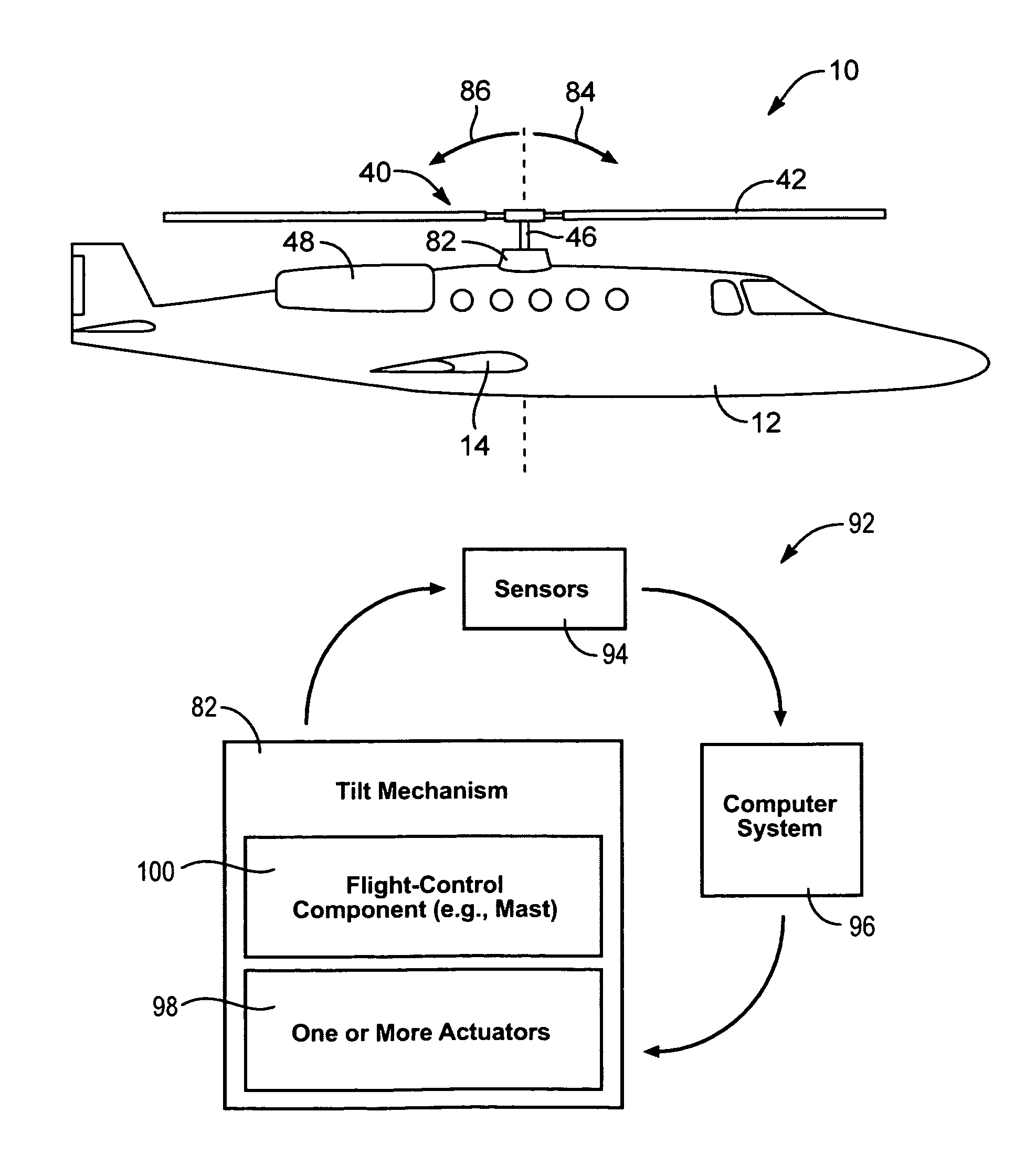
[0032]Alternatively, or in addition thereto, a control system may be configured to minimize the time needed for crossing certain natural frequencies of a rotor. In selected embodiments, a control system may include and manipulate controls over rotor longitudinal and lateral cyclic pitch, rotor collective pitch, rotor mast longitudinal tilt, rotor mast lateral tilt, fixed wing pitch, roll, and yaw controls (e.g., elevator, ailerons, rudder), rotorcraft thrust, or the like or combinations or sub-combinations thereof.
[0033]For example, during flight conditions when the rotational speed of a rotor is removed by a proper separation from a critical harmonic, a computer system running a aeromechanics model may continuously sets all available controls to achieve a best overall lift-to-drag ratio and minimize flapping. However, as a pilot transitions a rotorcraft through a critical harmonic, the aeromechanics model may temporarily transition from a first mode corresponding to best overall lift-to-drag ratio to a second mode corresponding to fastest change in rotational speed of the rotor.
[0034]In a second mode effecting a decrease in rotational speed of a rotor, a rotor may be tilted further forward than required for steady state autorotation. The result may be a rapid slowing in the rotational speed of the rotor to a value desired at the airspeed above the critical frequency crossing. In a second mode effecting an increase in rotational speed of a rotor, a rotor may be tilted further aft than required for steady state autorotation. The result may be a rapid increase in the rotational speed of the rotor to a value desired at the airspeed below the critical frequency crossing. Once a crossing has been made and a proper separation has been established, an aeromechanics model may transition back to a first mode corresponding to best overall lift-to-drag ratio.

Problems solved by technology

Flapping (i.e., bending of a rotor blade up and down) may cause relatively high moments and attendant stresses in a stiff blade-root attachment.
Additionally, flapping may also induce relatively high chord-wise loads due to Coriolis forces.
These loads may quickly fatigue a rotor.
During the crossing of any such natural frequency, the dynamic response of a rotor to periodic loads may amplified, leading to elevated structural loads and potentially high vibrations.

Method used


Image

  • Rotor-mast-tilting apparatus and method for lower flapping loads
  • Rotor-mast-tilting apparatus and method for lower flapping loads
  • Rotor-mast-tilting apparatus and method for lower flapping loads

Examples


Embodiment Construction

[0051]It will be readily understood that the components of the present invention, as generally described and illustrated in the drawings herein, could be arranged and designed in a wide variety of different configurations. Thus, the following more detailed description of the embodiments of the system and method of the present invention, as represented in the drawings, is not intended to limit the scope of the invention, as claimed, but is merely representative of various embodiments of the invention. The illustrated embodiments of the invention will be best understood by reference to the drawings, wherein like parts are designated by like numerals throughout.

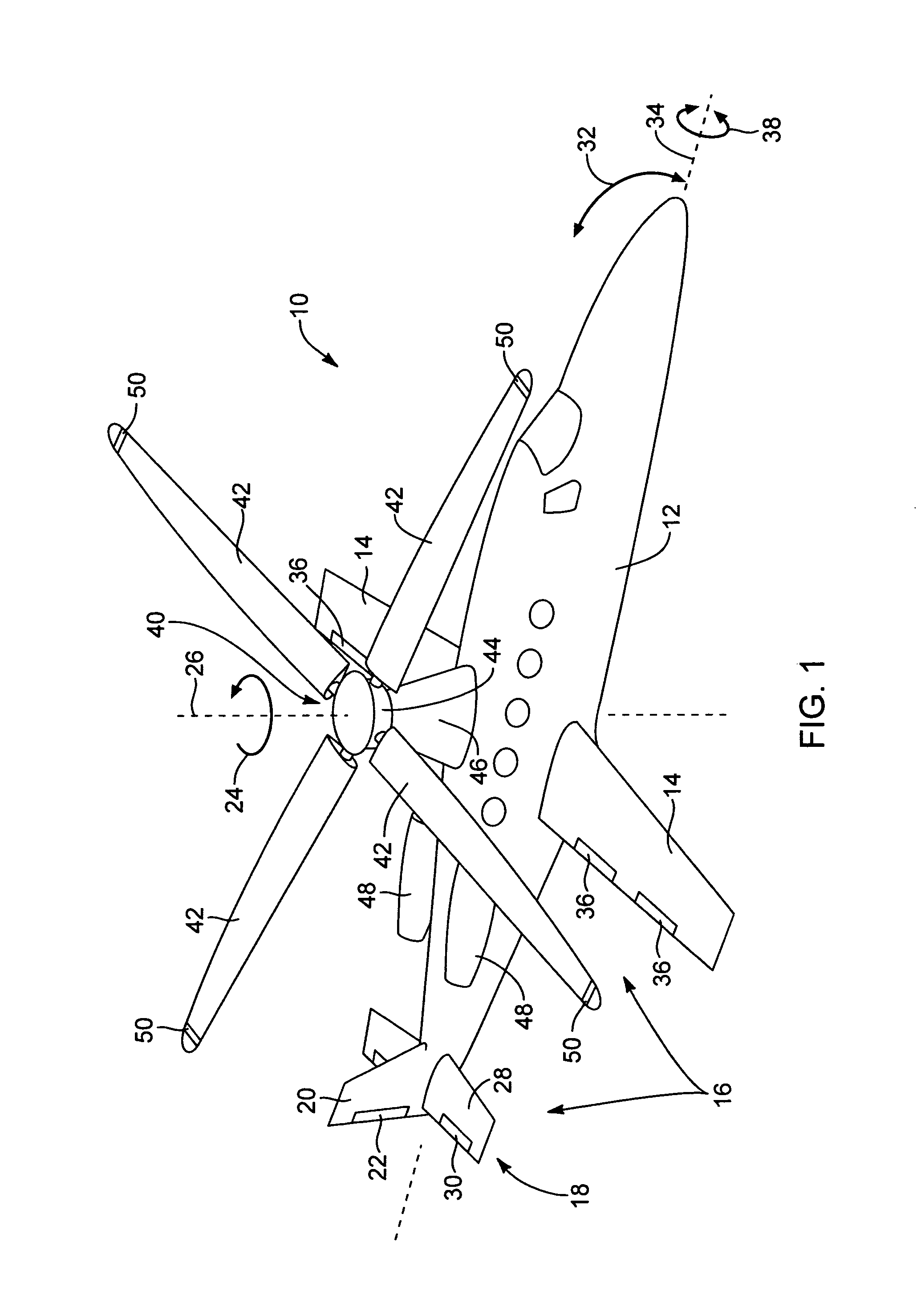
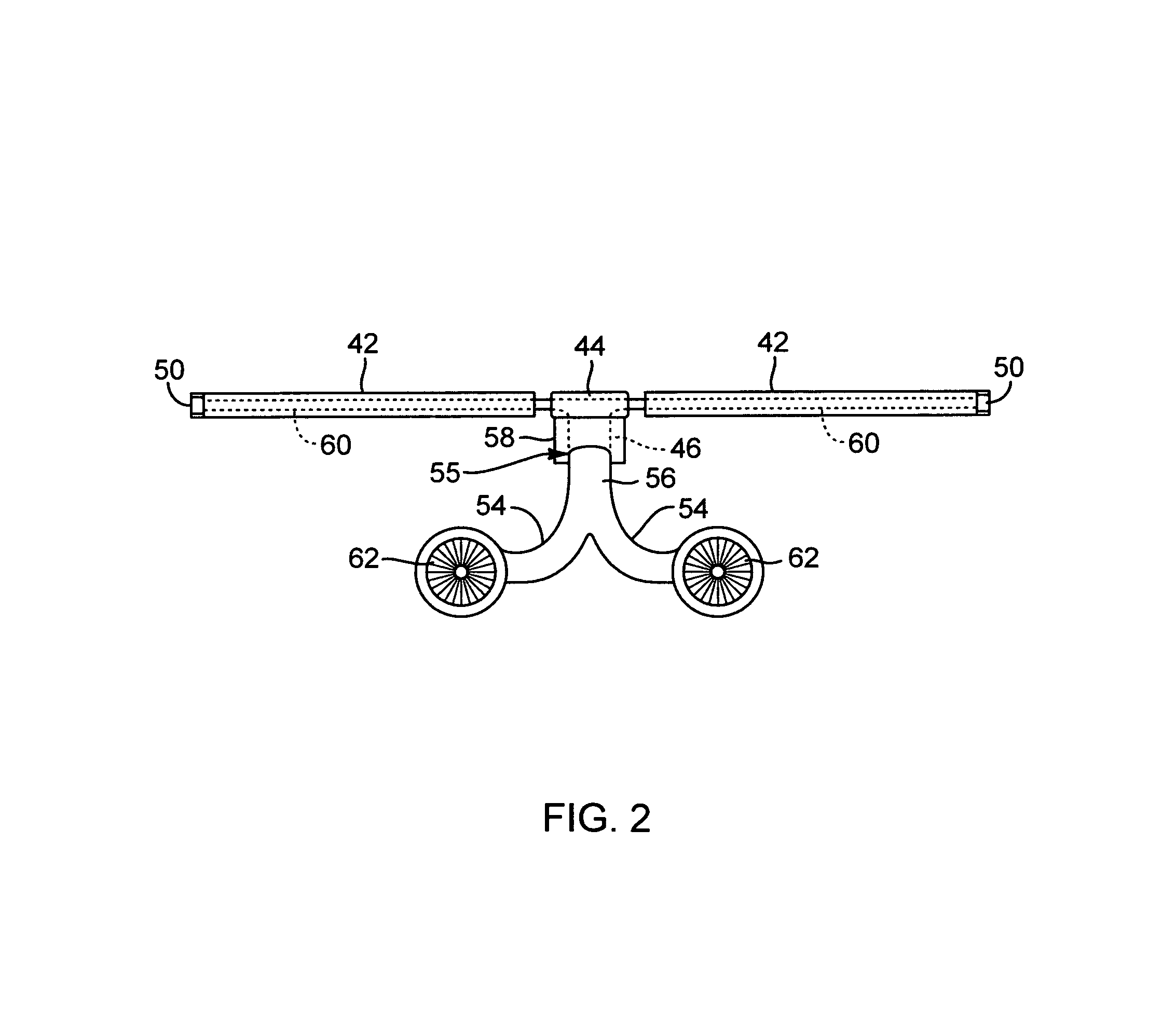
[0052]Referring to FIG. 1, a rotorcraft 10 in accordance with the present invention may include an airframe 12 defining a cabin for carrying an operator, passengers, cargo, or the like. The airframe 12 may include one or more fixed wings 14 or airfoils 14 providing lift to the rotorcraft 10. The wings 14 may be configured such t...


PUM


Abstract

A method and apparatus for reducing flapping loads imposed on a rotor are disclosed. The method may include flying a rotorcraft comprising an airframe, a rotor, a mast extending to connect the rotor to the airframe, a tilt mechanism, at least one sensor, and a computer system. The computer system may obtain in real time, from the at least one sensor, data characterizing at least one flapping load experienced by the rotor during the flying. Using the data, the computer system may issue at least one command to the tilt mechanism. In response to the command, the tilt mechanism may reorient the mast with respect to the airframe. This reorienting may lower the flapping load experienced by the rotor.

Description

RELATED APPLICATIONS[0001]This application: claims the benefit of U.S. Provisional Patent Application Ser. No. 61 / 575,196, filed on Aug. 17, 2011 and U.S. Provisional Patent Application Ser. No. 61 / 575,204, filed on Aug. 18, 2011. This application incorporates by reference all of the following applications: U.S. patent application Ser. No. 13 / 199,671, filed on Sep. 7, 2011, U.S. Provisional Patent Application Ser. No. 61 / 381,291, filed on Sep. 9, 2010, co-pending U.S. patent application Ser. No. 13 / 199,684, filed on Sep. 7, 2011, U.S. Provisional Patent Application Ser. No. 61 / 403,099, filed on Sep. 9, 2010, co-pending U.S. patent application Ser. No. 13 / 199,678, filed on Sep. 7, 2011, U.S. Provisional Patent Application Ser. No. 61 / 403,097, filed on Sep. 9, 2010, co-pending U.S. patent application Ser. No. 13 / 199,682, filed on Sep. 7, 2011, U.S. Provisional Patent Application Ser. No. 61 / 381,313, filed on Sep. 9, 2010, co-pending U.S. patent application Ser. No. 13 / 199,681, filed o...

Claims


Application Information

Patent Timeline
Patent Type & Authority Patents(United States)
IPC IPC(8): B64C27/52B64C27/02G05D19/00B64C27/00
CPCG05D19/00B64C27/02B64C27/52B64C27/001
Inventor KHAN, JEHAN ZEB
Owner SKYWORKS GLOBAL INC
Why Eureka
Try Eureka