Set of components for dental prosthetic restoration

Active Publication Date: 2021-05-06
ANTHOGYR
View PDF0 Cites 2 Cited by
  • Summary
  • Abstract
  • Description
  • Claims
  • Application Information

AI Technical Summary

Benefits of technology

[0007]A problem set by the present invention is to facilitate the production of a ceramic dental impla

Problems solved by technology

The machining of the ceramic is in fact extremely lengthy on account of its high degree of hardness.
In addition, the thread shape has to be modified with respect to a standard (metric) thread in order to limit the stress peaks that would result from machinin

Method used


Image

  • Set of components for dental prosthetic restoration
  • Set of components for dental prosthetic restoration
  • Set of components for dental prosthetic restoration

Examples


Embodiment Construction

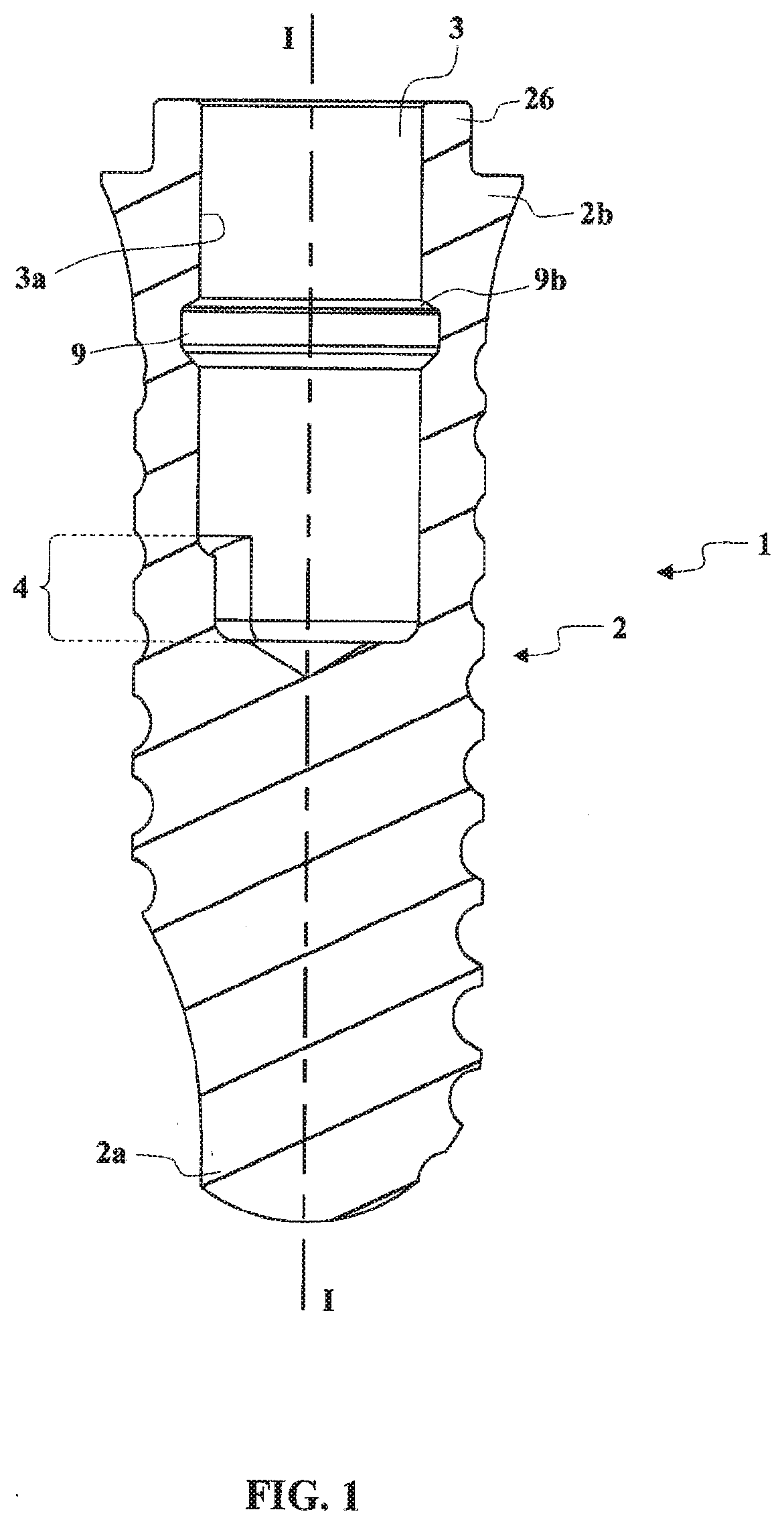
[0060]FIGS. 1 to 7 illustrate a first embodiment of a set 1 according to the present invention.

[0061]This set 1 has in the first instance a ceramic dental implant 2, as illustrated in FIG. 1, intended to be fitted in the upper jawbone or lower jawbone of a patient. The dental implant 2 extends along a first longitudinal axis I-I between a proximal end 2a and a distal end 2b, with an inner connection seat 3 extending from the distal end 2b in the direction of the proximal end 2a.

[0062]The inner connection seat 3 has at least one portion 4 of non-circular cross section.

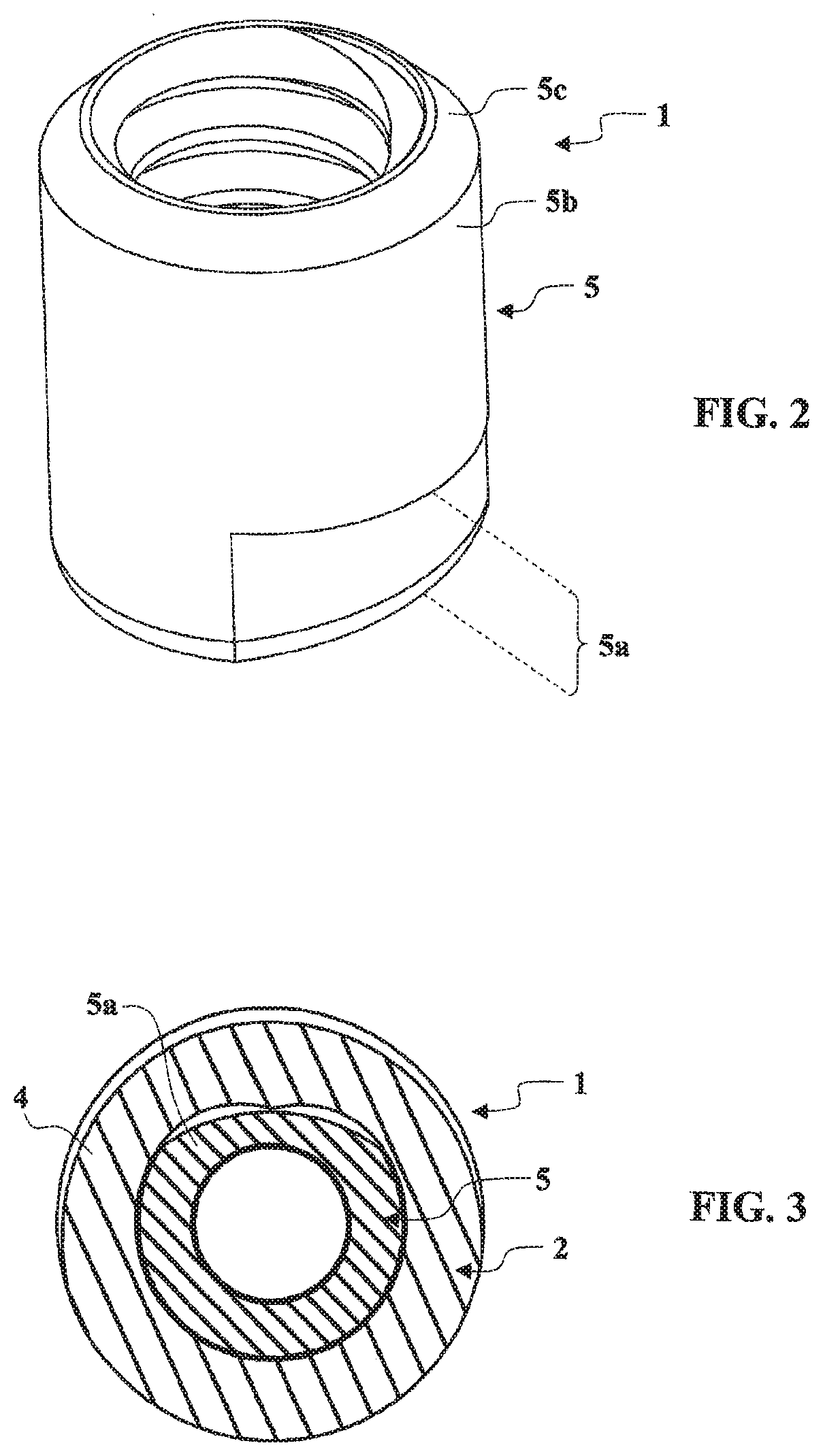
[0063]The set 1 comprises in the second instance an internally threaded insert 5, as illustrated in FIG. 2, configured in such a way as to be mounted in the portion 4 of non-circular cross section of the inner connection seat 3 of the dental implant 2 (see FIG. 6) by being indexed in rotation there about the first longitudinal axis I-I. More precisely, the internally threaded insert 5 has a proximal portion 5a of non-c...


PUM


Abstract

A set of components for dental prosthetic restoration includes a ceramic dental implant having an internal connecting receiving space. An internally threaded insert is added into the internal connecting receiving space of the dental implant, and rotatably indexed. It is held by a fixing part forming an axial abutment opposing an extraction of the internally threaded insert out of the inner connection receiving space.

Description

TECHNICAL FIELD OF THE INVENTION[0001]The present invention relates to the field of dental prosthetic restoration, and relates more particularly to a dental implant made of ceramic.[0002]Dental implants are known which are made of metallic material, such as titanium or a titanium alloy, and which are intended to be fitted in the upper jawbone or lower jawbone of a patient, extending along a first longitudinal axis between a proximal end and a distal end, with an inner connection seat extending from the distal end in the direction of the proximal end.[0003]The inner connection seat is generally threaded internally over part of its length in order to receive, by screwing, a fixing screw intended to ensure definitive fixation of a dental component such as an abutment or a transfixed prosthesis core having an outer form substantially in the shape of a tooth. The fixing screw routinely has an outer thread of metric profile.[0004]While the formation of an inner thread in the inner connect...

Claims


Application Information

Patent Timeline
IPC IPC(8): A61C8/00
CPCA61C8/0012A61C8/0063A61C8/0062A61C8/0068A61C8/0022A61C8/0048A61C8/0056A61C8/0065A61C13/2656
Inventor RICHARD, HERVÉ
Owner ANTHOGYR
Why Eureka
Try Eureka