Work vehicle and control method for work vehicle

a technology for work vehicles and control methods, which is applied in the direction of soil shifting machines/dredgers, mechanical equipment, transportation and packaging, etc., can solve the problems of weakened braking force of the vehicle by the engine brake, excessive engine speed, etc., and achieve the effect of suppressing a decrease in braking force and preventing over-rotation of the engin

Active Publication Date: 2021-05-13
KOMATSU LTD
View PDF0 Cites 2 Cited by
  • Summary
  • Abstract
  • Description
  • Claims
  • Application Information

AI Technical Summary

Benefits of technology

[0020]According to the present invention, it is possible to prevent over-rotation of the engine and to suppress a decrease in braking force due to the engine brake.

Problems solved by technology

In that case, if the acceleration force of the vehicle by gravity is strong, there is a possibility that the engine speed may be excessive (hereinafter referred to as “over-rotation state”).
However, as described above, when the transmission gear ratio is reduced by reducing the displacement of the traveling motor or increasing the displacement of the traveling pump, the braking force of the vehicle by the engine brake is weakened.

Method used


Image

  • Work vehicle and control method for work vehicle
  • Work vehicle and control method for work vehicle
  • Work vehicle and control method for work vehicle

Examples


Embodiment Construction

)

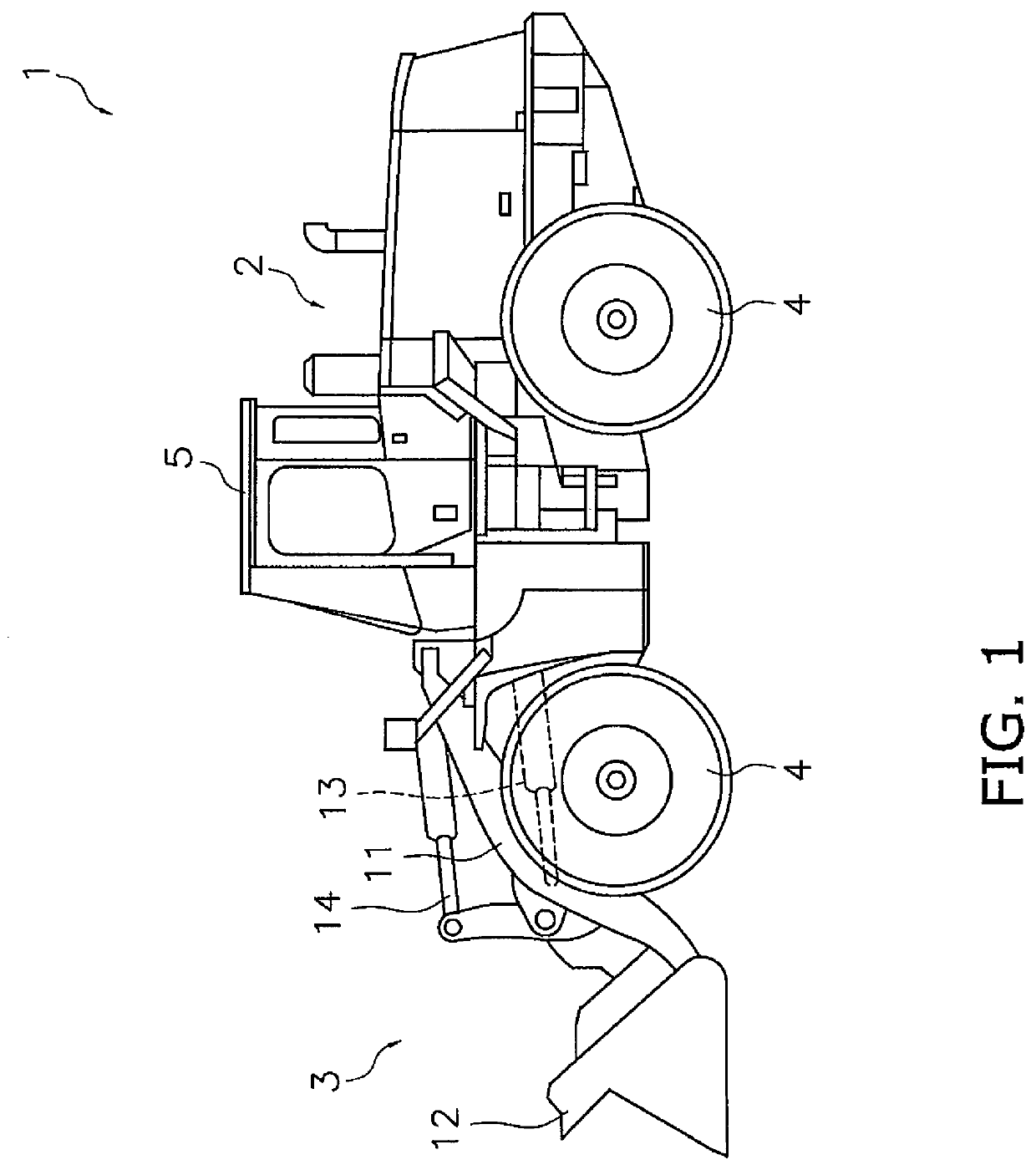
[0037]Hereinafter, a work vehicle 1 according to an embodiment of the present invention will be described using the drawings. FIG. 1 is a side view of the work vehicle 1. The work vehicle 1 is a wheel loader. The work vehicle 1 includes a vehicle body 2, a work implement 3, a plurality of traveling wheels 4, and a cab 5. The work implement 3 is attached to the front of the vehicle body 2. The work implement 3 includes a boom 11, a bucket 12, a lift cylinder 13 and a bucket cylinder 14.

[0038]The boom 11 is rotatably attached to the vehicle body 2. The boom 11 is driven by the lift cylinder 13. The bucket 12 is rotatably attached to the boom 11. The bucket 12 is moved up and down by the bucket cylinder 14. The cab 5 is disposed on the vehicle body 2. The plurality of traveling wheels 4 are rotatably attached to the vehicle body 2.

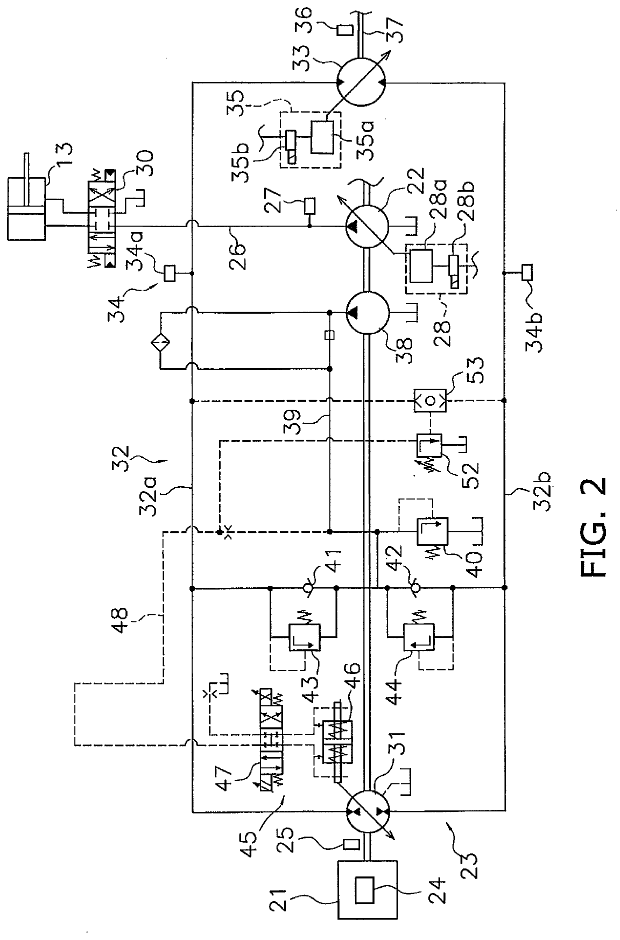
[0039]FIG. 2 is a block diagram showing a configuration of a drive system mounted on work vehicle 1. The work vehicle 1 includes an engine 21, a work implem...


PUM


Abstract

A work vehicle includes an engine, a traveling pump driven by the engine, a hydraulic circuit connected to the traveling pump, a traveling motor connected to the traveling pump via the hydraulic circuit, a rotational speed sensor configured to output a signal indicative of engine speed a hydraulic pressure sensor configured to output a signal indicative of hydraulic pressure of the hydraulic circuit, a controller. The controller receives the signals from the rotational speed sensor and the hydraulic pressure sensor. The controller determines whether the engine is in an over-rotation state based on engine speed. The controller determines an upper limit value of a displacement of the traveling pump based on hydraulic pressure of the hydraulic circuit. The controller limits the displacement of the traveling pump to the upper limit value or less upon determining that the engine is in the over-rotation state.

Description

CROSS-REFERENCE TO RELATED APPLICATIONS[0001]This application is a U.S. National stage application of International Application No. PCT / JP2018 / 020534, filed on May 29, 2018. This U.S. National stage application claims priority under 35 U.S.C. § 119(a) to Japanese Patent Application No. 2017-125375, filed in Japan on Jun. 27, 2017, the entire contents of which are hereby incorporated herein by reference.BACKGROUNDField of the Invention[0002]The present invention relates to a work vehicle and a control method for a work vehicle.Background Information[0003]Some work vehicles are equipped with a hydrostatic transmission. The hydrostatic transmission includes a traveling pump, a traveling motor, and a hydraulic circuit connecting the traveling pump and the traveling motor. The traveling pump is driven by the engine and discharges hydraulic fluid. The hydraulic fluid discharged from the traveling pump is supplied to the traveling motor via the hydraulic circuit. The traveling motor is dri...

Claims


Application Information

Patent Timeline
Patent Type & Authority Applications(United States)
IPC IPC(8): E02F9/22F16H59/36F16H59/68
CPCE02F9/2235E02F9/2253E02F9/2296F16H61/431F16H59/68E02F9/2285E02F9/2292F16H59/36E02F9/22F16H61/465F16H2059/366F16H2059/6861B60Y2200/41B60Y2200/415F16H61/472F16H61/468
Inventor OASA, TAKAHISA
Owner KOMATSU LTD
Why Eureka
Try Eureka