
Cartridge seal assembly for rotational equipment

a technology of rotating equipment and seals, applied in the direction of efficient propulsion technologies, mechanical equipment, machines/engines, etc., can solve the problems of increasing the rubbing speed of bearing compartment seals, increasing the wear and/or heat generation of seals, and occupying design space for engines

Active Publication Date: 2021-05-13
RTX CORP
View PDF0 Cites 2 Cited by
  • Summary
  • Abstract
  • Description
  • Claims
  • Application Information

AI Technical Summary

Benefits of technology

The present disclosure provides assemblies for rotational equipment such as gas turbine engines. These assemblies include a housing, carrier, spring element, and seal element. The carrier is partially or fully received within the housing and is configured to translate axially along a centerline relative to the housing. The spring element is arranged within the housing and is configured to bias the carrier axially away from the housing along the centerline. The seal element is mounted to the carrier and is completely axially overlapped by the housing. The assembly may also include an anti-rotation feature to prevent or limit rotation of the carrier, a spacer to secure the seal element within the housing, and a snap ring stopper to secure the spacer. The seal element may be a carbon seal element or a washer. The assembly may also include a rotating structure rotatable about the centerline and a seal land to seal a gap between the carrier and the seal land. The technical effects of the present disclosure include improved sealing performance and reduced wear and tear on the seal elements.

Problems solved by technology

Seal assemblies for main shaft bearing compartments of gas turbine engines take up design space.
Design space reduction is a challenge for future aircraft engine products.
Furthermore, future aircraft engine products may require cycles that have significantly higher rotor speeds thereby increasing bearing compartment seal rubbing speeds.
Such increased rubbing speeds may increase seal wear and / or heat generation, which may in turn shorten engine products cycles.
Traditional seal assemblies may have high spring loads leading to higher seal contact pressures and greater heat generation, resulting in increased wear of the seal and decreased seal life.

Method used


Image

  • Cartridge seal assembly for rotational equipment
  • Cartridge seal assembly for rotational equipment
  • Cartridge seal assembly for rotational equipment

Examples


Embodiment Construction

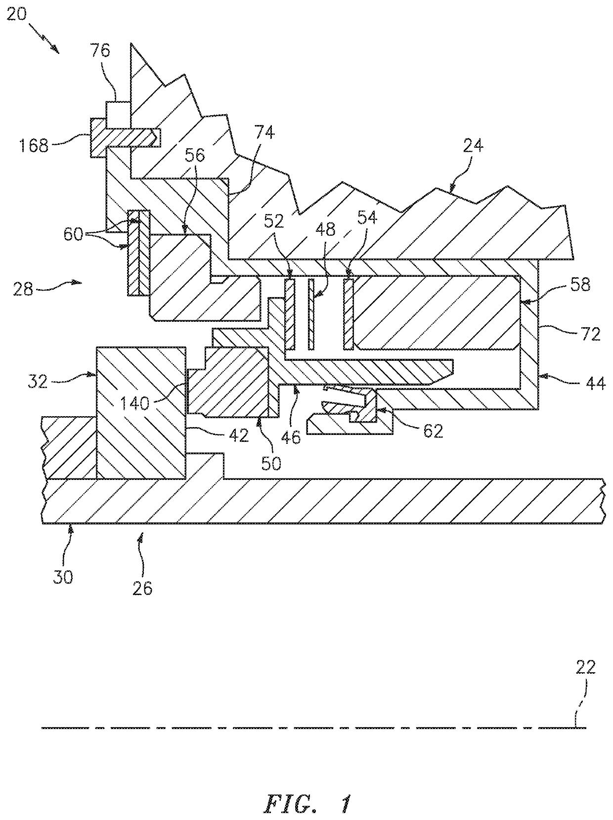
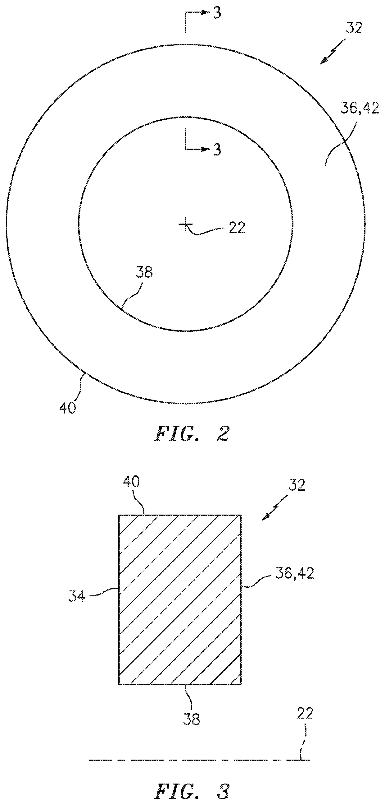
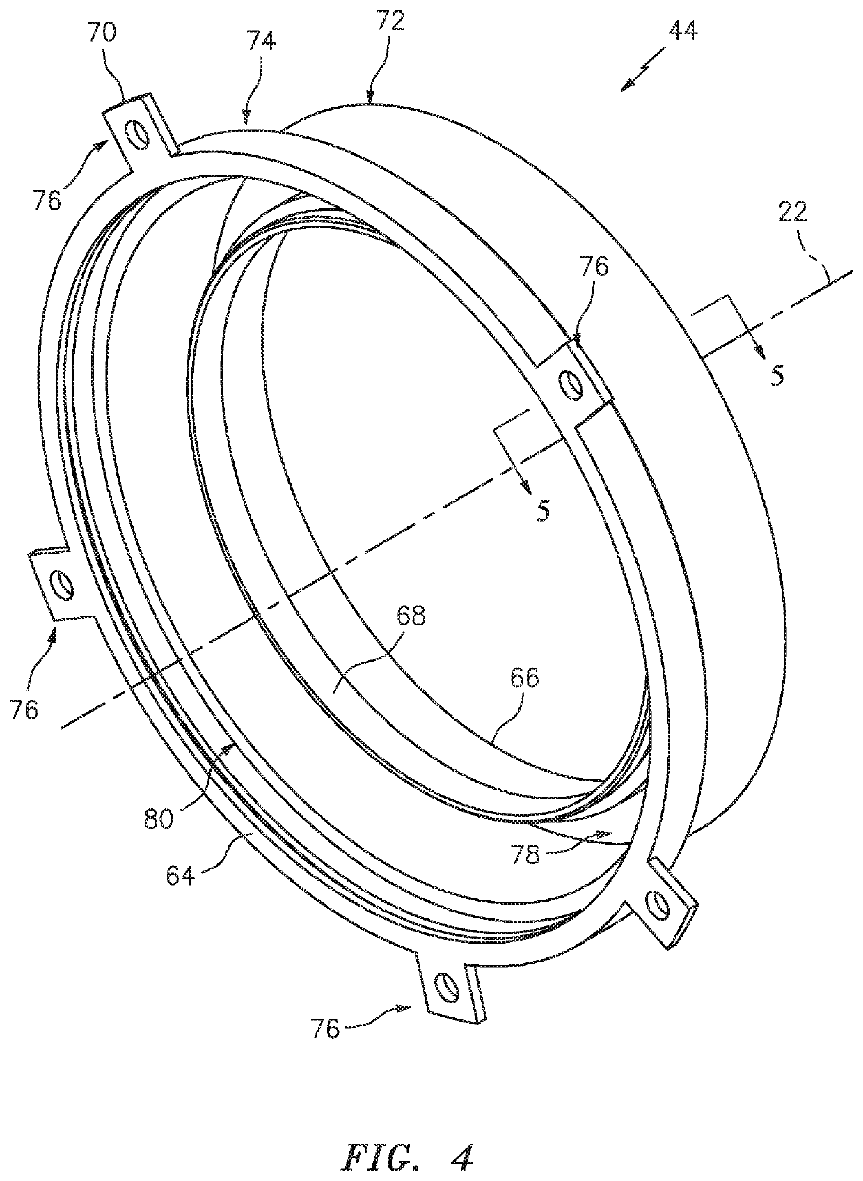
[0046]FIG. 1 illustrates an assembly 20 for rotational equipment with an axial centerline 22, which centerline 22 may also be an axis of rotation (e.g., a rotational axis) for one or more components of the assembly 20. An example of such rotational equipment is a gas turbine engine for an aircraft propulsion system, an exemplary embodiment of which is described below in further detail with respect to FIG. 19. However, the assembly 20 of the present disclosure is not limited to such an aircraft application nor a gas turbine engine application. The assembly 20, for example, may alternatively be configured with rotational equipment such as an industrial gas turbine engine, a wind turbine, a water turbine or any other apparatus in which a seal is provided between a stationary structure and a rotating structure; e.g., a rotor.

[0047]The assembly 20 of FIG. 1 includes a stationary structure 24, a rotating structure 26 and a seal assembly 28; e.g., a compact, cartridge seal assembly. The se...


PUM


Abstract

An assembly includes a housing, a carrier, a spring element and a seal element. The housing includes a bore and an annular groove that extends axially along a centerline into the housing from the bore. The carrier projects axially along the centerline into the annular groove. The carrier is configured to translate axially along the centerline relative to the housing. The spring element is arranged within the annular groove. The spring element is configured to bias the carrier axially away from the housing along the centerline. The seal element is mounted to the carrier and arranged within the bore.

Description

BACKGROUND OF THE DISCLOSURE1. Technical Field[0001]This disclosure relates generally to rotational equipment and, more particularly, to a seal assembly for sealing a gap between a rotating component and a stationary component.2. Background Information[0002]A gas turbine engine typically includes various seal assemblies for sealing gaps between stationary components and rotating components. Various types of seal assemblies are known in the art.[0003]Seal assemblies for main shaft bearing compartments of gas turbine engines take up design space. Design space reduction is a challenge for future aircraft engine products. Furthermore, future aircraft engine products may require cycles that have significantly higher rotor speeds thereby increasing bearing compartment seal rubbing speeds. Such increased rubbing speeds may increase seal wear and / or heat generation, which may in turn shorten engine products cycles.[0004]Traditionally, a seal contact load, which creates seal contact pressure...

Claims


Application Information

Patent Timeline
Patent Type & Authority Applications(United States)
IPC IPC(8): F16J15/34F02C7/28
CPCF16J15/3452F16J15/3464F05D2240/55F05D2220/323F02C7/28F16J15/348F16J15/38F01D11/003F01D25/183F05D2240/58Y02T50/60
Inventor SONOKAWA, MASAYOSHIZIMMITTI, JONATHAN F.SHUAIB, NASR A.
Owner RTX CORP
Learn More