Rotary Joint Shroud Having Set-Up Gauge and Seal Wear Indicator

a technology of rotary joints and gauges, which is applied in the direction of adjustable joints, mechanical equipment, papermaking, etc., can solve the problems of reducing the thickness affecting the performance of the seal ring, so as to avoid or reduce corrosion

Active Publication Date: 2021-05-20
KADANT JOHNSON LLC
View PDF0 Cites 0 Cited by
  • Summary
  • Abstract
  • Description
  • Claims
  • Application Information

AI Technical Summary

Benefits of technology

[0013]The shroud may be connected to the end flange via a snap fit, wherein the end flange has tabs that extend from the end flange, are received by, and extend into corresponding apertures provided in the shroud. The shroud may further have at least one vent having apertures that extend through the shroud to view and allow fluid to escape through the at least one vent should any fluid inadvertently escape from the rotary joint. The shroud may be positioned to cover and house the compression springs to avoid or reduce corrosion to the compression springs.

Problems solved by technology

The installation of the prior art rotary joints is a time consuming and difficult process.
This requires an installer accurately measure the distance between the end flange and the piston, which can be difficult in light of the structure of the rotary joint, and the surrounding equipment as well as the biasing forces of the compression springs.
Due to the revolving wear plate rotating against the seal ring, the seal ring evidentially begins to wear.
Nonetheless, the thickness of the seal ring eventually diminishes thereby requiring that the seal ring be replaced.
However, there are few or no effective indicators as to when the seal ring must be replaced.
For instance, previous wear indicators have included tabs that are fastened to the spring-biased piston, wherein the tab eventually contacts the wear plate once the seal ring becomes excessively worn.
However, papermill facilities are often quite loud, and thus, the noise made by the tab engaging the wear plate may be difficult to hear.
In addition, the tab may shear off from the piston once the tab engages the revolving wear plate thereby prohibiting any noise from being made and possibly causing the sheared off tab from damaging the seal ring or other components of the rotary joint.
Such measurements and inspections are time consuming, difficult, and create inefficiencies that are undesirable in an industrial environment.
Since the compression springs are commonly fabricated from metallic materials, the compression springs often rust or become corroded due to the steam and condensate that collect on the compression springs as well as other chemicals that may be utilized in conjunction with the paper manufacturing process.
This requires that the compression springs either be replaced or cleaned on a regular basis, which is a time-consuming and costly process that creates inefficiencies in the paper manufacturing process.

Method used


Image

  • Rotary Joint Shroud Having Set-Up Gauge and Seal Wear Indicator
  • Rotary Joint Shroud Having Set-Up Gauge and Seal Wear Indicator
  • Rotary Joint Shroud Having Set-Up Gauge and Seal Wear Indicator

Examples


Embodiment Construction

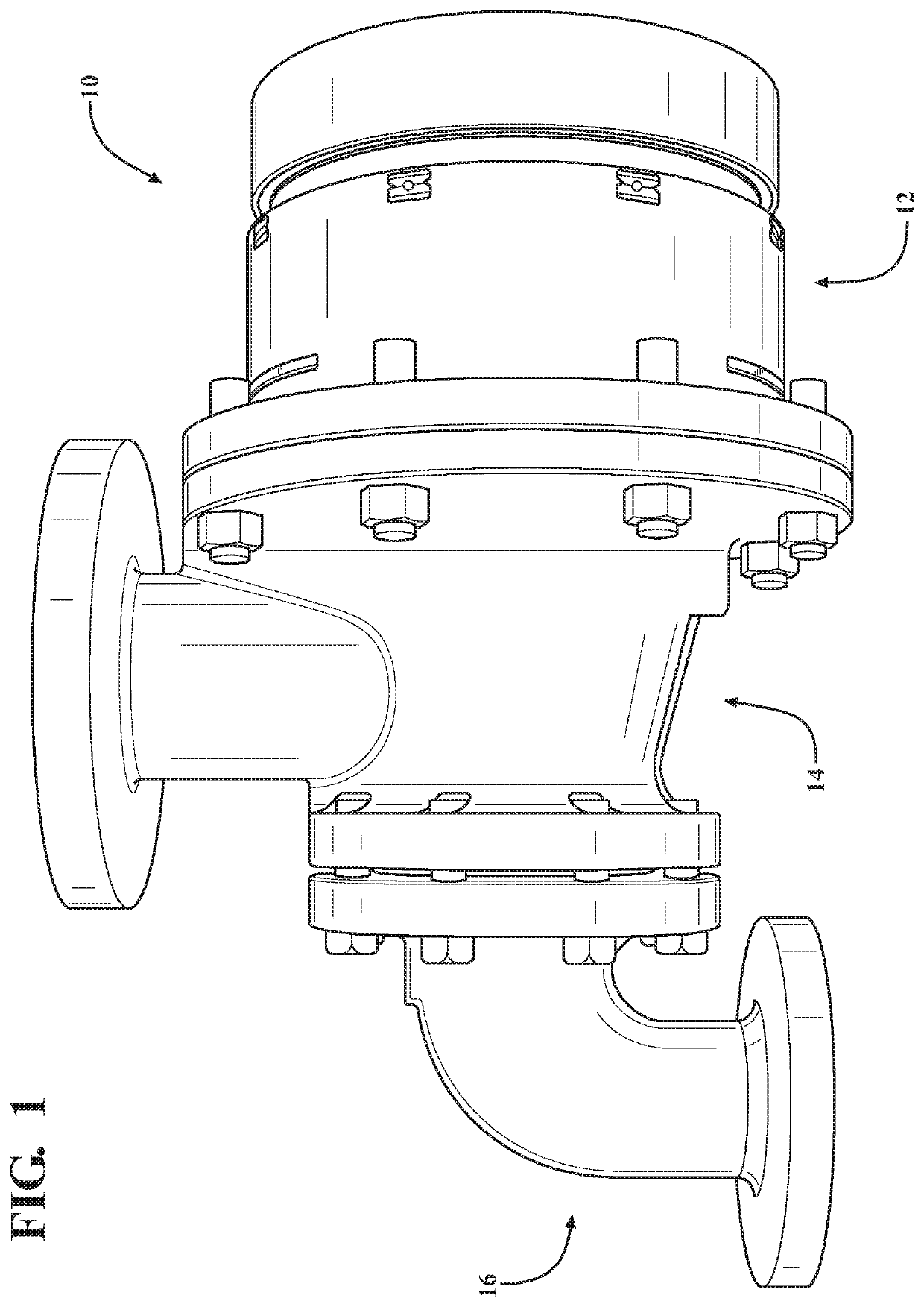
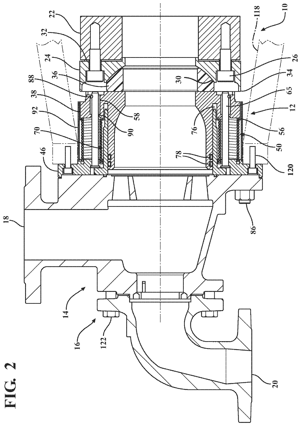
[0024]The present disclosure relates to a rotary joint or rotary joint cartridge 10 which may be used in combination with a rotating drying cylinder (not shown) of a paper manufacturing machine (not shown). The rotary joint 10 provides a sealed connection to the drying cylinder to communicate pressurized steam, water, and air to and from the drying cylinder. As seen in FIG. 1, the rotary joint 10 has a body portion 12 having one end connected to the drying cylinder and an opposite end connected to an inlet coupling or joint body 14 which receives pressurized steam and air from a pressurized source (not shown). An outlet coupling 16 is connected to and in communication with the inlet coupling 14 to direct steam, condensate, and air from the drying cylinder. Separate passageways (not shown) are provided to allow pressurized steam and air to flow from the inlet coupling 14 to the drying cylinder. A syphon (not shown) is installed down the center of the inlet coupling 14, seated against...


PUM


Abstract

A rotary joint for connecting a stationary body to a rotating body. The rotary joint has a rotatable wear plate connectable to the rotating body and a seal ring seated in the wear plate. A spring-biased piston engages the seal ring against the wear plate by compressed springs between an end flange and the piston. The end flange and the piston are at least partially disposed within a shroud, wherein the shroud has at least one aperture extending there through. Alignment rings are formed on the piston and viewable through the aperture in the shroud to confirm the proper distance between the end flange and the piston and the proper force applied to the piston. A seal wear indicator is connected to the piston and moves between an exposed position, wherein the seal ring is not worn, and a non-exposed position, wherein the seal ring is worn.

Description

CROSS-REFERENCE TO RELATED APPLICATIONS[0001]The following U.S. formal patent application claims priority from U.S. provisional patent application No. 62 / 935,764 filed on Nov. 15, 2019.FIELD OF THE INVENTION[0002]The present disclosure pertains generally to a piston-type rotary joint for use primarily in the paper manufacturing industry, and in particular, a rotary joint having a shroud that provides a set-up gauge for properly installing the rotary joint and a seal wear indicator to enhance the preventative maintenance of the rotary joint.BACKGROUND[0003]Rotary joints are commonly used in the paper manufacturing industry to couple sources of steam and condensate with a rotating drying cylinder of a paper-manufacturing machine. The rotary joint provides a pressure-tight joint formed between a revolving journal of the drying cylinder and the stationary construction used to transfer the steam and condensate into and out of the drying cylinder. A seal ring is positioned and pressured a...

Claims


Application Information

Patent Timeline
Patent Type & Authority Applications(United States)
IPC IPC(8): F16J15/38F16J15/34
CPCF16J15/38F16J15/3452F16L27/082F16J15/3492D21F5/10D21F5/08D21F5/021
Inventor ROMERO, ISAAC E.IVES, ALAN T.NEWLAND, ZACHARY S.
Owner KADANT JOHNSON LLC
Why Eureka
Try Eureka