Control method and robot system

a robot and control method technology, applied in the field of control methods and robot systems, can solve the problems of inability to identify inability to operate based on the attached replacement hand, and inability to secure security, so as to and reduce the operating speed of the robot arm

Active Publication Date: 2021-05-27
SEIKO EPSON CORP
View PDF6 Cites 0 Cited by
  • Summary
  • Abstract
  • Description
  • Claims
  • Application Information

AI Technical Summary

Benefits of technology

[0007]A control method according to the present disclosure is a control method for a robot including a robot arm including an arm to which one of a plurality of end effectors is detachably attachable, the robot arm being driven based on an operation program, and a detecting section configured to detect motion of the robot arm. The control method including: an acquiring step for acquiring information concerning the plurality of end effectors and acquiring the operation program; and a driving step for driving the robot arm based on the operation program acquired in the acquiring step. In the driving step, speed of a speed estimation target part is calculated for each of the plurality of end effectors based on a detection result of the detecting section. When it is determined that, in a result of the calculation, speed of the speed estimation target part moving at highest speed when the robot arm is driven by the operation program is equal to or higher than predetermined speed, operating speed of the robot arm is reduced.
[0008]A control method according to the present disclosure is a control method for a robot including a robot arm including an arm to which one of a plurality of end effectors is detachably attachable, the robot arm being driven based on an operation program, and a detecting section configured to detect motion of the robot arm. The control method including: an acquiring step for acquiring information concerning the plurality of end effectors and acquiring the operation program; a calculating step for calculating speed of a speed estimation target part for each of the plurality of end effectors based on the information acquired in the acquiring step and calculating, based on a detection result of the detecting section, in a result of the calculation, speed of the speed estimation target part moving at highest speed at time when the robot arm is driven by the operation program; and a driving step for driving the robot arm based on the operation program acquired in the acquiring step. In the driving step, when it is determined that the calculation result is equal to or higher than predetermined speed, operating speed of the robot arm is reduced.
[0009]A robot system according to the present disclosure includes: a robot arm including an arm to which one of a plurality of end effectors is detachably attachable, the robot arm being driven based on an operation program; a detecting section configured to detect motion of the robot arm; an acquiring section configured to acquire information concerning the end effectors and acquire the operation program; a calculating section configured to calculate speed of a speed estimation target part for each of the plurality of end effectors based on the information acquired by the acquiring section; a driving control section configured to drive the robot arm based on the operation program; and a comparing section configured to calculate, when the robot arm is driven by the operation program, based on a detection result of the detecting section, speed of the speed estimation target part moving at highest speed and compare a result of the calculation and predetermined speed. When the comparing section determines that the calculation result is equal to or higher than the speed, the driving control section reduces operating speed of the robot arm.

Problems solved by technology

However, a replacement hand not including switching means for identifying a type of the replacement hand is attached to the robot, the robot cannot identify the attached replacement hand and cannot operate based on the attached replacement hand.
Therefore, security cannot be secured.

Method used


Image

  • Control method and robot system
  • Control method and robot system
  • Control method and robot system

Examples


first embodiment

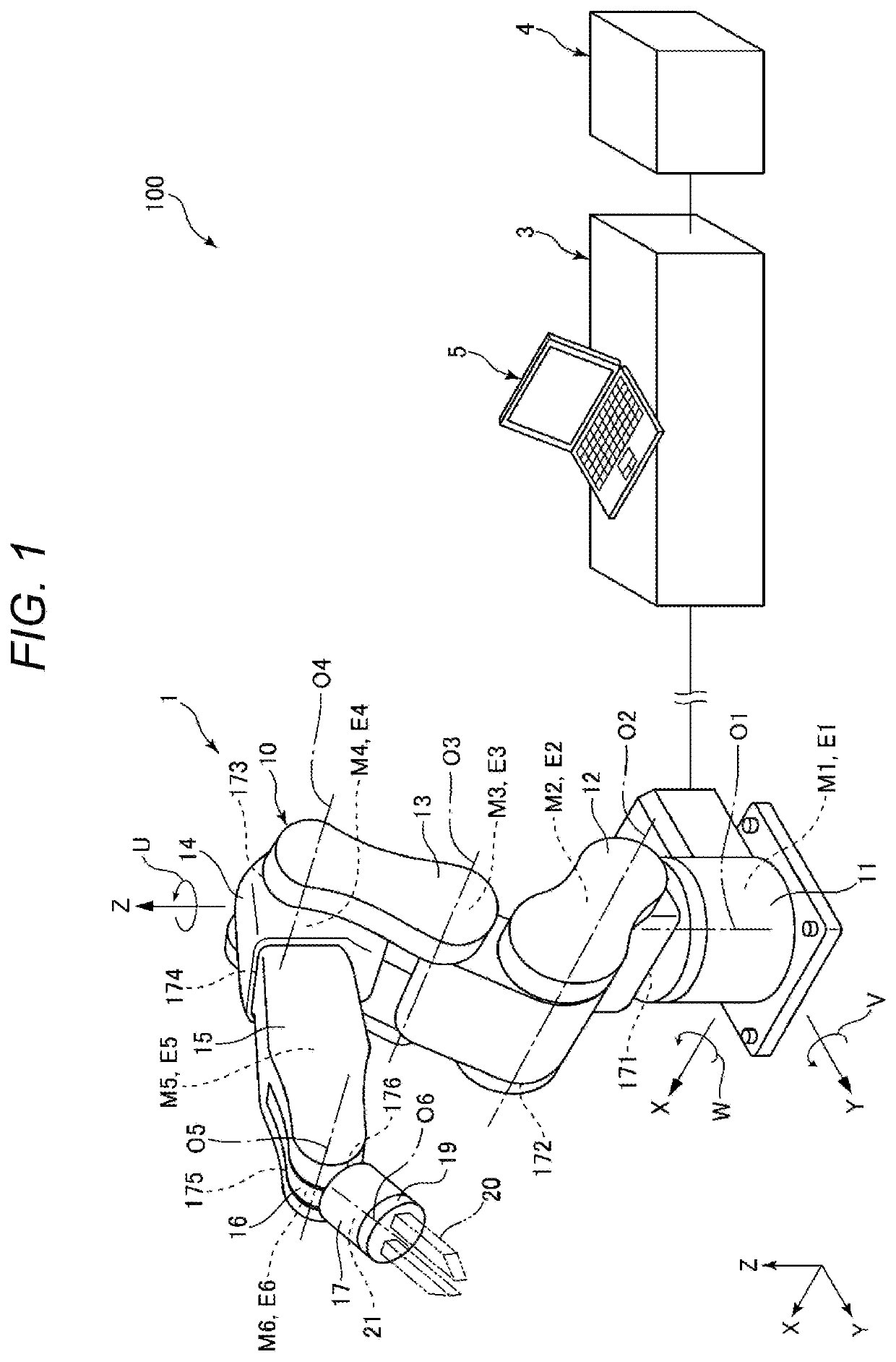
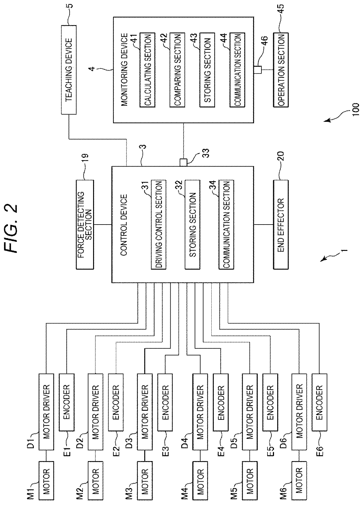
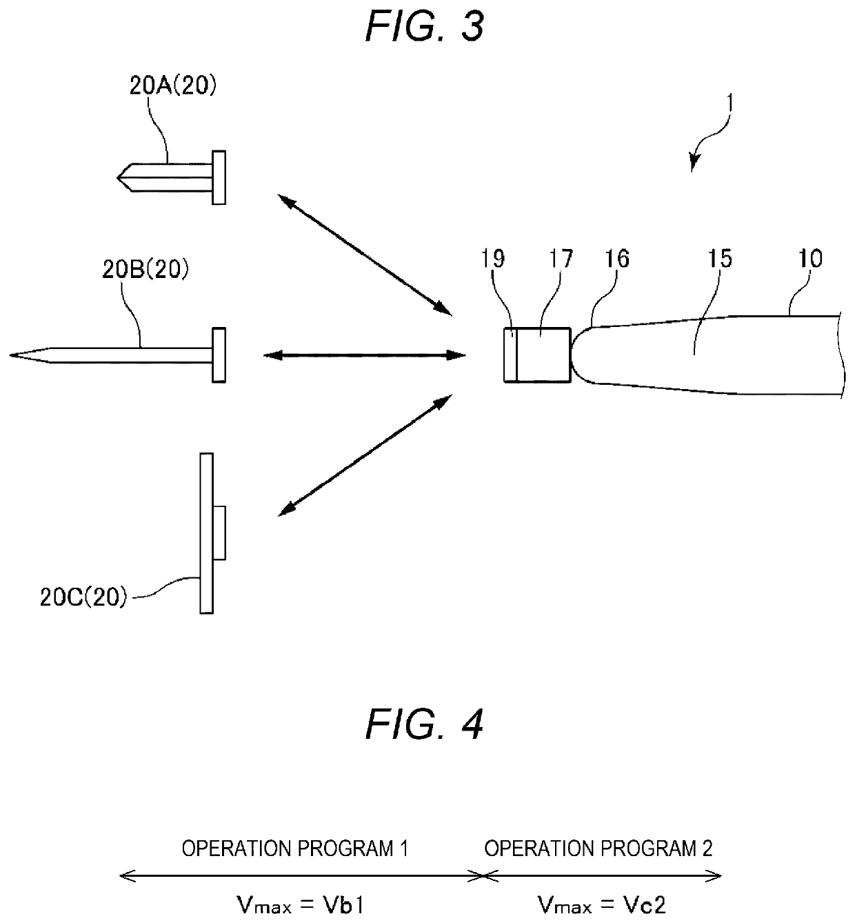
[0025]FIG. 1 is a diagram showing an overall configuration of a robot system in a first embodiment. FIG. 2 is a block diagram of the robot system shown in FIG. 1. FIG. 3 is a diagram showing an end effector attached to a robot arm included in a robot shown in FIG. 1. FIG. 4 is a conceptual diagram for explaining a unit operation program of an operation program executed by the robot system shown in FIG. 1. FIGS. 5 to 10 are side views showing a state in which the robot shown in FIG. 1 is executing the operation program. FIG. 11 is a flowchart for explaining a control operation of the robot system shown in FIG. 1.

[0026]A control method and a robot system according to the present disclosure are explained in detail below based on preferred embodiments shown in the accompanying diagrams. In the following explanation, for convenience of explanation, an X axis, a Y axis, and a Z axis are illustrated as three axes orthogonal to one another. In the following explanation, a direction parallel...

second embodiment

[0119]FIG. 12 is a flowchart for explaining a control operation of a robot system in a second embodiment.

[0120]The second embodiment is explained below. In the following explanation, differences from the first embodiment are mainly explained. Explanation about similarities is omitted.

[0121]As shown in FIG. 12, in this embodiment, the driving control section 31 sequentially executes step S201, step S202, step S203, step S204, step S205, step S206, step S207, and step S208.

[0122]Step S201 is the same as step S101. Step S202 is the same as step S102. Step S203 is the same as step S103. Step S204 is the same as step S105. Step S205 is the same as step S104. Step S206 is the same as step S106. Step S207 is the same as step S107. Step S208 is the same as step S108.

[0123]That is, in this embodiment, prior to executing an operation program, the driving control section 31 respectively calculates, based on information acquired in an acquiring step, speeds of speed estimation target parts of t...

modification 1

[0128]FIG. 14 is a block diagram showing a modification 1 centering on hardware of a robot system.

[0129]In FIG. 14, an overall configuration of a robot system 1006 in which a computer 63 is directly coupled to the robot 1 is shown. Control of the robot 1 is directly executed by a processor present in the computer 63 reading out a command present in a memory.

[0130]Therefore, the computer 63 can be grasped as the “control device”.


PUM


Abstract

A control method includes an input step for inputting information concerning a setting angle of a robot arm of a robot including the robot arm and a force detecting section configured to detect force applied to the robot arm and a calculating step for calculating a proper force detection parameter of the force detecting section at the setting angle of the robot arm based on a first force detection parameter of the force detecting section corresponding to setting at a first setting angle of the robot arm and a second force detection parameter of the force detecting section corresponding to setting at a second setting angle different from the first setting angle of the robot arm.

Description

[0001]The present application is based on, and claims priority from JP Application Serial Number 2019-214668, filed Nov. 27, 2019, the disclosure of which is hereby incorporated by reference herein in its entirety.BACKGROUND1. Technical Field[0002]The present disclosure relates to a control method and a robot system.2. Related Art[0003]For example, JP-A-6-344285 (Patent Literature 1) discloses a robot including a replacement hand including switching means for performing switching setting corresponding to a type of the replacement hand, a robot main body to which the replacement hand is selectively attached, and robot-main-body controlling means for controlling the robot main body.[0004]In the robot disclosed in Patent Literature 1, the robot-main-body controlling means identifies the type of the replacement hand based on the switching means of the replacement hand attached to the robot main body. Consequently, the robot can recognize which replacement hand is attached. It is possibl...

Claims


Application Information

Patent Timeline
Patent Type & Authority Applications(United States)
IPC IPC(8): B25J9/16B25J15/04B25J13/08
CPCB25J9/1664B25J13/088B25J9/1602B25J15/04B25J19/0095G05B2219/39468B25J9/1612B25J9/1674
Inventor YAMADA, YOSHIHITOKINOSHITA, HIROFUMI
Owner SEIKO EPSON CORP
Why Eureka
Try Eureka