
Air exhaust device, air conditioning system and the control method therefor

a technology of air exhaust device and air conditioning system, which is applied in the field of air conditioning, can solve the problems of large air purification filter element, and health hazards of particles such as pm2.5, and achieve the effects of reducing the operating speed of the fan device, eliminating or alleviating the harm of formaldehyde, and greatly improving air quality

Pending Publication Date: 2021-05-06
CARRIER CORP
View PDF1 Cites 0 Cited by
  • Summary
  • Abstract
  • Description
  • Claims
  • Application Information

AI Technical Summary

Benefits of technology

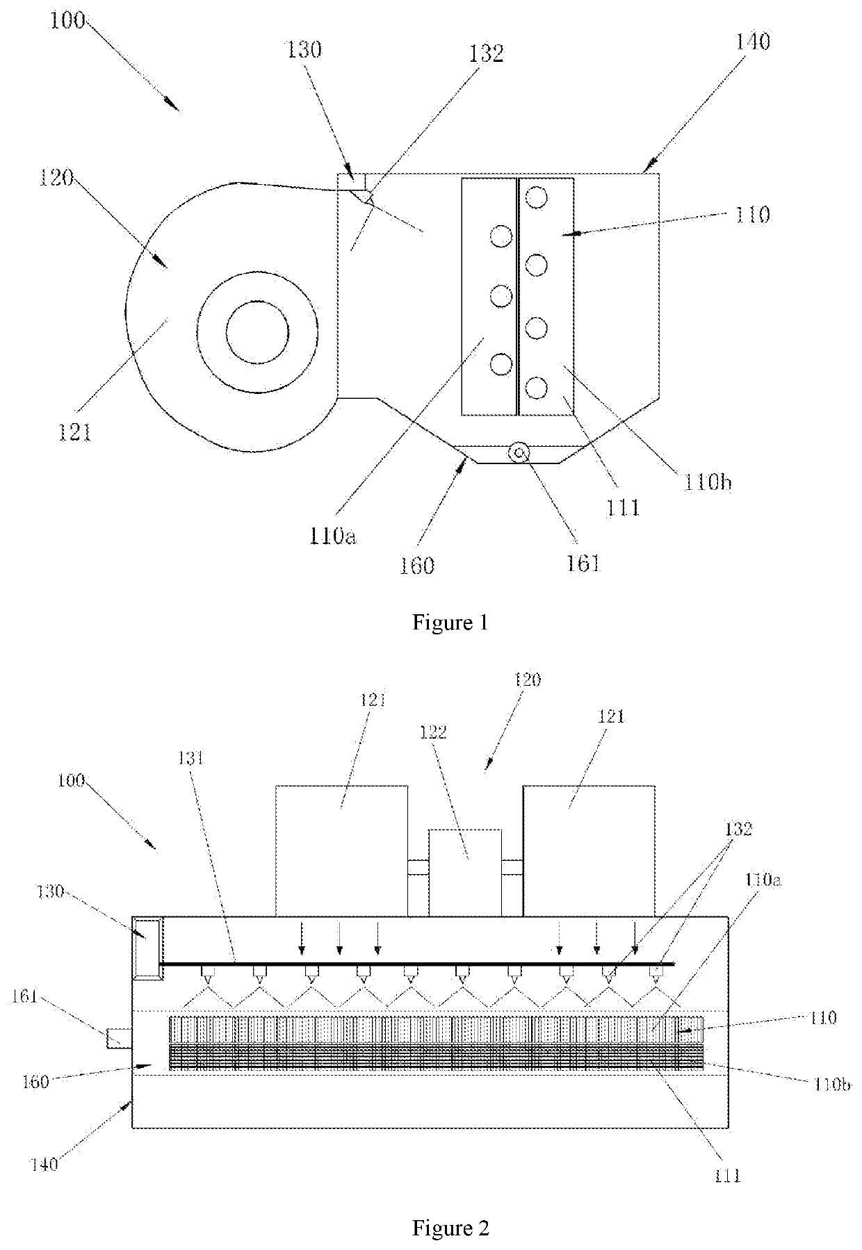
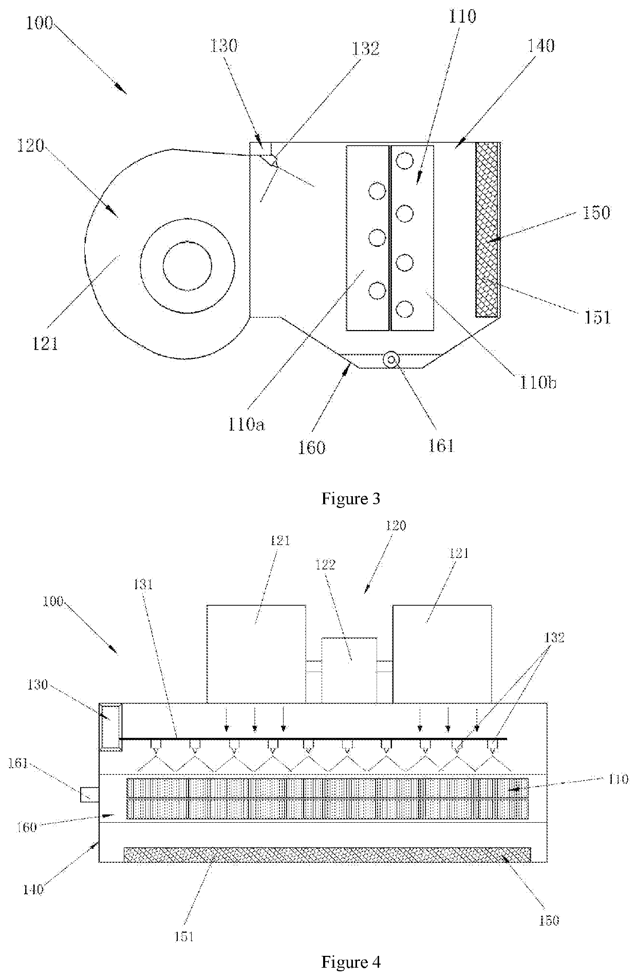
The patent describes an air conditioning system that includes a control method and an air outlet device with a formaldehyde removal part. The control method includes a heat exchange self-cleaning mode that reduces the operating speed of the fan device to wash PM2.5 aggregated particles settled on the heat exchanger. The air outlet device includes the formaldehyde removal part that catalyzes the air flowing through, decomposing formaldehyde into water and carbon dioxide to effectively eliminate or alleviate the harm of formaldehyde. This results in improved air quality and avoids impact on human health. The formaldehyde removal part is efficient, with almost no loss and no need to replace consumables. The patent provides a solution for an integrated device that can reliably achieve air conditioning and purification.

Problems solved by technology

For example, particulates such as PM2.5, formaldehyde and other volatile organic compounds (VOCs) are all harmful to health and are extremely common in the existing living environment.
However, on the one hand, considering that the structural space of the air conditioning equipment is limited, it is difficult to carry a large air purification filter element; on the other hand, considering that the air conditioning equipment is usually in a fixed state once the installation is completed, the replacement of the filter element in it is relatively complicated.
Therefore, there is no effective solution to integrate the two at present.

Method used


Image

  • Air exhaust device, air conditioning system and the control method therefor
  • Air exhaust device, air conditioning system and the control method therefor

Examples


Embodiment Construction

[0021]First, it should be noted that the composition, operating principle, characteristics, advantages, and the like of the air outlet device, air conditioning system, and control method therefor according to the present application are illustrated below by examples. However, it should be understood that all the descriptions are given for illustrative purposes only, and therefore should not be construed as limiting the present invention.

[0022]In addition, for any single technical feature described or implied in the embodiments mentioned herein, or any single technical feature displayed or implied in each drawing, the present application still allows any continued arbitrary combination or deletion of these technical features (or the equivalents thereof) without any technical obstacles, thereby obtaining more other embodiments of the present application that may not be directly mentioned herein.

[0023]Furthermore, with regard to the present application, it should be noted that the anio...


PUM


Abstract

An air outlet device, an air conditioning system, and a control method therefor. The air outlet device is for use in an air conditioning system, and includes: an air outlet device for an air conditioning system, including: a heat exchanger that exchanges heat with the air flowing through; a fan device that drives the air to flow through the heat exchanger; a formaldehyde removal part coated with a formaldehyde removal coating that can catalyze the decomposition of formaldehyde into water and carbon dioxide; a housing for accommodating the heat exchanger, the fan device, and the formaldehyde removal part; and a controller for controlling the start and stop of the fan device. According to the air outlet device, the air conditioning system, and the control method therefor of the present application, the air is purified by providing a formaldehyde removal part in the housing of the air outlet device.

Description

FOREIGN PRIORITY[0001]This application claims priority to Chinese Patent Application No. 201911071462.1, filed Nov. 5, 2019, and all the benefits accruing therefrom under 35 U.S.C. § 119, the contents of which in its entirety are herein incorporated by reference.TECHNICAL FIELD OF INVENTION[0002]The present application relates to the field of air conditioning. More specifically, the present application relates to an air outlet device with an air purification function, an air conditioning system, and a control method therefor.BACKGROUND OF THE INVENTION[0003]Air conditioning equipment belongs to a well-developed technical field, and it plays a role in regulating air temperature and humidity. Air purification equipment also belongs to a field that is newly emerging and rapidly developing in recent years, and it plays a role in improving air quality. The rapid development of air purification equipment has benefited from human beings' increasing attention to the health of the living env...

Claims


Application Information

Patent Timeline
Patent Type & Authority Applications(United States)
IPC IPC(8): F24F3/16F24F13/30F24F13/20F24F11/77F24F8/10
CPCF24F3/166F24F13/30F24F3/1603F24F2110/65F24F11/77F24F2003/1682F24F2013/205F24F13/20F24F11/65F24F11/89F24F13/28F24F2110/64F24F8/10F24F8/167F24F8/192Y02B30/70F24F8/30F24F7/007
Inventor ZHAO, DANZHANG, XINGLEIHUANG, WEI
Owner CARRIER CORP
Learn More