Valve timing regulator

a timing regulator and valve technology, applied in non-mechanical valves, valve arrangements, machines/engines, etc., can solve the problems of reducing the operating speed of the rotor and increasing the leakage rate, and achieve the reduction of the rotor operating speed, the effect of reducing the linear expansion coefficient, and enhancing the ease of attachment of the assist spring

Inactive Publication Date: 2012-07-05
MITSUBISHI ELECTRIC CORP
View PDF5 Cites 0 Cited by
  • Summary
  • Abstract
  • Description
  • Claims
  • Application Information

AI Technical Summary

Benefits of technology

[0008]According to the invention, in order to enhance the ease of attachment of the assist spring, it is configured that the clearance formed by the length in the axial direction of the holding member provided on the vane side and the length in the axial direction of the case is set to be equal to or greater than the sum of the increment of the length in the axial direction in consideration of the tilt of the holding member produced by the gap between the holding member and the recess, and the increment due to the thermal expansion; thus, even when the holding member tilts within the range of the gap provided between the member and the recess in the vane or shoe, or even when there occurs the tilt due to the thermal expansion upon an increase of oil temperature (the rotor and case are formed out of iron-based materials and have a smaller linear expansion coefficient than the holding member made of resin), the tilt of the holding member during the assembly of the member and the assist spring, or the tilt due to rotor operations or vibrations; the following inconveniences can be prevented reliably: the occurrence of a stretched state between a cover and a housing at the two ends, the reduction in the rotor operating speed due to the friction, the increase in leakage due to the wear on the sliding surface of the cover, and so on.

Problems solved by technology

Therefore, in a practical use, the holding member may tilt within the range of a gap between the holding member and the recess or is fallen in a stretched state between a cover and a housing at the two ends thereof due to the thermal expansion or the like; thus, there is a problem such that inconveniences such as a reduction in a rotor operating speed due to the friction and an increase in leakage due to the wear on the sliding surface between the cover and the housing are concerned.

Method used


Image

  • Valve timing regulator
  • Valve timing regulator
  • Valve timing regulator

Examples


first embodiment

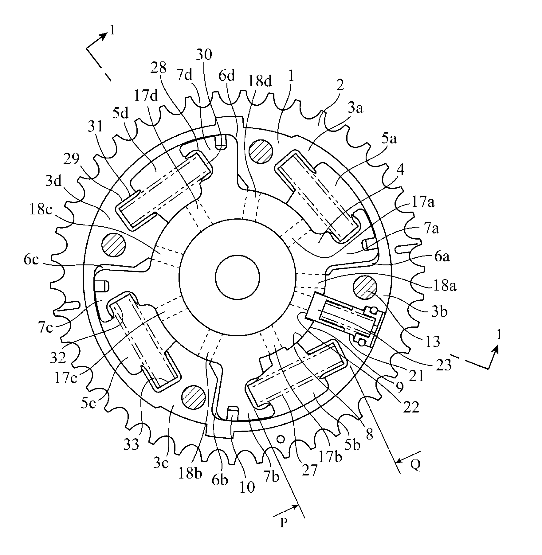
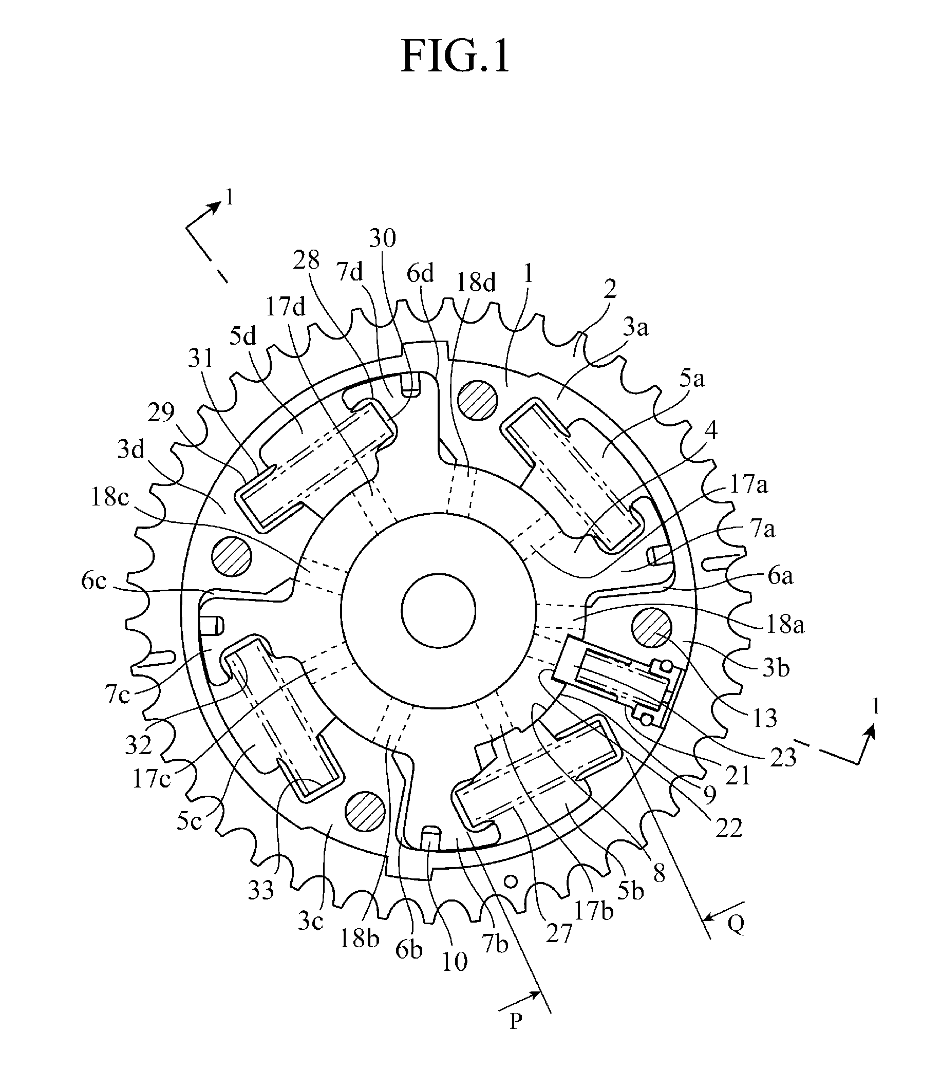
[0014]FIG. 1 is a radial direction sectional view of a valve timing adjusting apparatus of a first embodiment in the present invention, taken along a line 2-2 in FIG. 2, and FIG. 2 is an axial direction sectional view of the valve timing adjusting apparatus of the first embodiment in the invention, taken along a line 1-1 in FIG. 1.

[0015]In the drawings, a sprocket portion 2 for transmitting a driving force from a crank (not shown) is formed on the outer periphery of a case 1, and shoes 3a to 3d forming hydraulic chambers are provided in the inner peripheral portion of the case 1. Vanes 7a to 7d that divide the four hydraulic chambers formed by the shoes 3a to 3d of the case 1 into advance-side hydraulic chambers 5a to 5d and retard-side hydraulic chambers 6a to 6d, and that are also hydraulic pressure reception portions are disposed on the outer side of a rotor 4 at intervals of substantially 90 degrees. In the rotor 4, a boss portion 9 is in sliding contact with an inner sliding po...


PUM


Abstract

A valve timing adjusting apparatus includes: recesses provided opposite to the wall surfaces in a circumferential direction of a shoe and a vane in an advance hydraulic chamber; a holding member insertion-disposed into the recesses from an axial direction; and an assist spring disposed between the holding member on the shoe side and the holding member on the vane side to urge a rotor in an advance direction, and further a clearance formed by a length in the axial direction of the holding member provided on the vane side and a length in the axial direction of the case is set to not less than a sum of an increment of the length in the axial direction in consideration of a tilt of the holding member produced by a gap between the holding member and recess, and an increment due to the thermal expansion.

Description

TECHNICAL FIELD[0001]The present invention relates to a valve timing adjusting apparatus that changes automatically opening and closing timings of an exhaust valve in response to an operating condition of an internal combustion engine.BACKGROUND ART[0002]This type of valve timing adjusting apparatus includes: a camshaft for driving an exhaust valve of an internal combustion engine to open and close; a case that is rotatably provided on the camshaft and rotationally driven by an output of the internal combustion engine; a rotor that is relatively rotatably housed inside the case and coupled to the camshaft; and a locking means that constrains a relative rotation between the case and the rotor when operated by a mechanical urging force, and releases the constraint when operated by a fluid control pressure applied from an internal hydraulic chamber in a direction opposing the mechanical urging force.[0003]With the aim of applying the thus constructed valve timing adjusting apparatus to...

Claims


Application Information

Patent Timeline
Patent Type & Authority Applications(United States)
IPC IPC(8): F01L9/02
CPCF01L2001/34483F01L1/3442
Inventor HASE, HIROFUMI
Owner MITSUBISHI ELECTRIC CORP
Why Eureka
Try Eureka