Multipolar connector

a multi-polar, connector technology, applied in the direction of coupling/case, coupling device connection, electrical apparatus, etc., can solve the problems of inconvenience for users and inconvenience in particular

Active Publication Date: 2021-05-27
CONEXTIVITY GRP SA
View PDF5 Cites 1 Cited by
  • Summary
  • Abstract
  • Description
  • Claims
  • Application Information

AI Technical Summary

Benefits of technology

[0028]In embodiments, the connector according to the invention comprises a locking system making it possible to block the rotation of the plug with respect t

Problems solved by technology

However, having to align one component with respect to the other one before connecting them is an inconvenience for the user.
This inconvenience is particularly notable if the components o

Method used


Image

  • Multipolar connector
  • Multipolar connector
  • Multipolar connector

Examples


Embodiment Construction

[0030]The invention will be better understood in the following description of different embodiments and technical features thereof, said embodiments being given as non-limiting examples.

BRIEF DESCRIPTION OF THE FIGURES

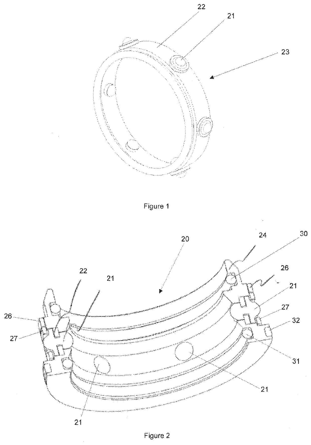
[0031]FIG. 1 illustrates a perspective view of a part of an embodiment of the invention;

[0032]FIG. 2 illustrates a cross-sectional and perspective view from below of a locking module according to an embodiment;

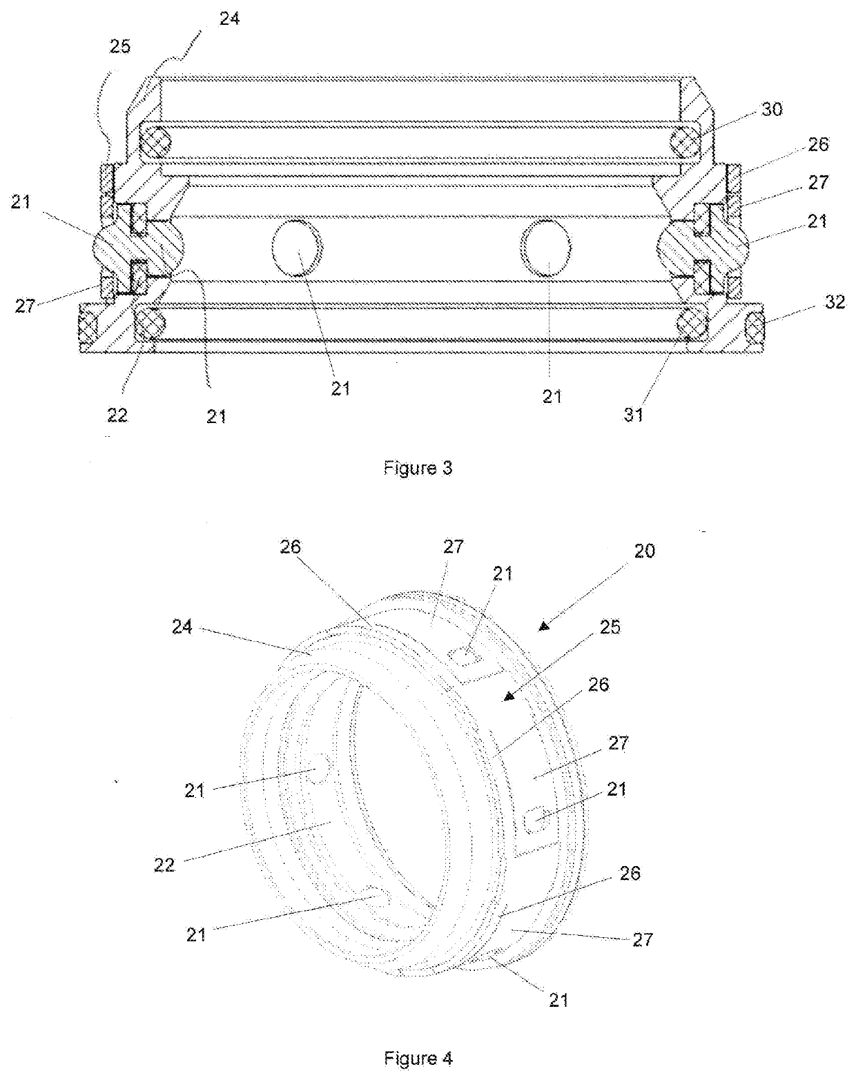
[0033]FIG. 3 illustrates a cross-sectional side view of a locking module according to an embodiment;

[0034]FIG. 4 illustrates a perspective rear view of a locking module according to an embodiment;

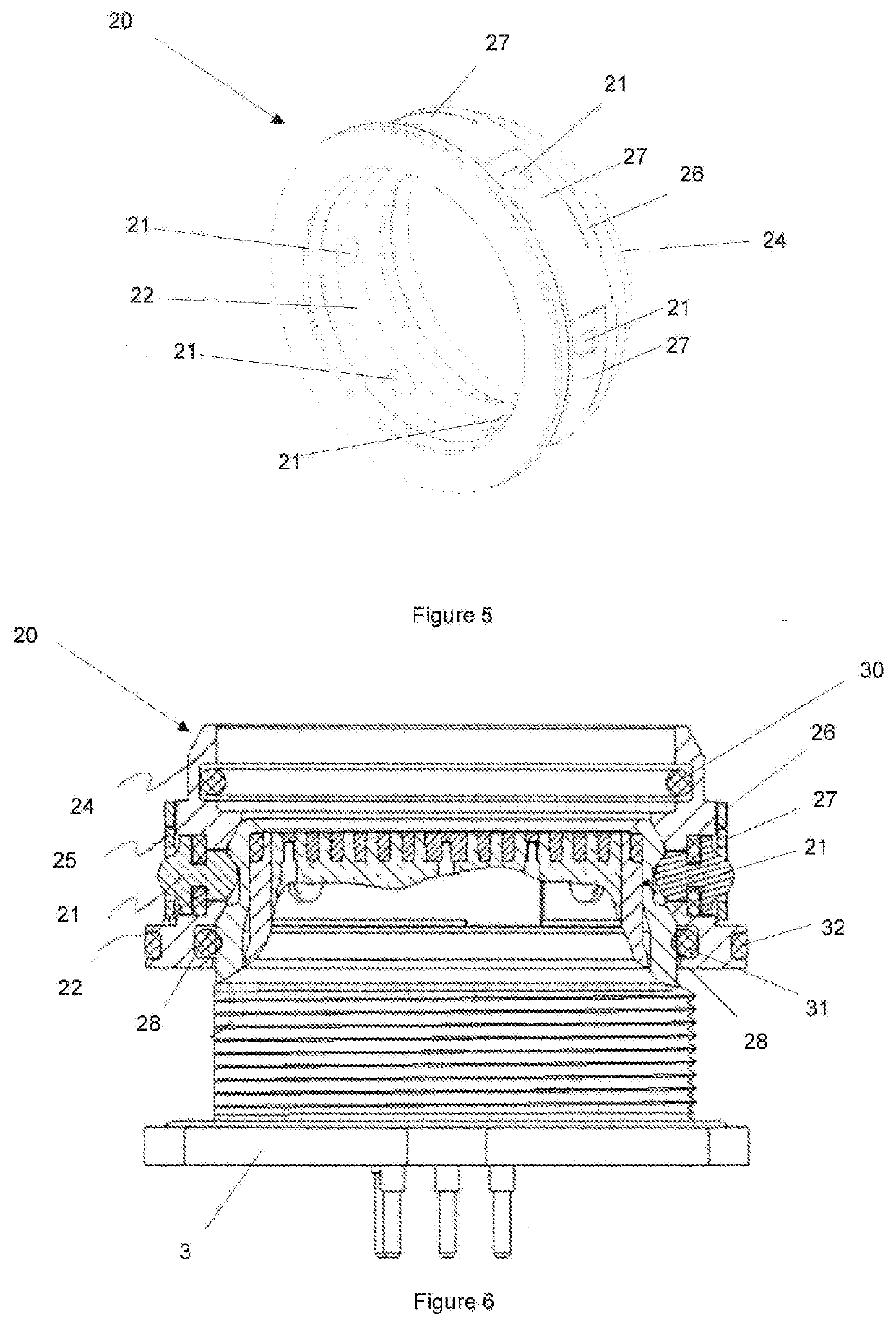
[0035]FIG. 5 illustrates a perspective front view of a locking module according to an embodiment;

[0036]FIG. 6 illustrates a side view in partial cross-section of a module mounted on a plug connected to a socket according of an embodiment of the invention;

[0037]FIG. 7 illustrates a top view of a socket;

[0038]FIG. 8 illustrates an embodiment of a connector comprising a plu...


PUM


Abstract

A connector comprising a cylindrically shaped socket and a plug that may be connected to the socket in a removable manner, in which a plurality of contacts are disposed being mounted in a contact block. It comprises a ring with ogive shaped parts (21) assembled in a membrane (22), the ogive shaped parts and the membrane being covered by a locking spring (25).

Description

CORRESPONDING APPLICATION[0001]The present application claims the priority of the earlier application number PCT / IB2018 / 052391, filed on Apr. 6, 2018 in the name of Fischer Connectors Holding SA, the content of this earlier application being incorporated by reference in its entirety in the present patent application.FIELD OF THE INVENTION[0002]The present invention relates to connectors, in particular multipolar electric connectors, used for example in the field of electrical wiring. For example, the connectors in question are used for / in fields of application necessitating both reliability and flexibility, such as applications of the wearable type, for example the clothing or equipment of people moving in difficult environments (workers, emergency service, soldiers and security forces, etc . . . ) or any other similar use.PRIOR ART[0003]In most cases, the use of a multipolar connector necessitates that the two principal components of the connector (for example a component containin...

Claims


Application Information

Patent Timeline
IPC IPC(8): H01R13/627H01R13/52H01R13/635
CPCH01R13/6276H01R13/635H01R13/5219H01R24/38
Inventor STORIONE, SAVINOCONVERT, NICOLASBUCHILLY, JEAN-MARIE
Owner CONEXTIVITY GRP SA
Why Eureka
Try Eureka