Supercharge Your Innovation With Domain-Expert AI Agents!

Bone conduction speaker and compound vibration device thereof

a bone conduction speaker and vibration device technology, applied in the field of bone conduction speakers, can solve the problems of limited tone quality, difficult to improve the tone quality of current bone conduction speakers containing current vibration devices, etc., and achieve the effect of reducing costs

Active Publication Date: 2021-06-03
SHENZHEN SHOKZ CO LTD
View PDF1 Cites 2 Cited by
  • Summary
  • Abstract
  • Description
  • Claims
  • Application Information

AI Technical Summary

Benefits of technology

The present invention is providing an improved bone conduction speaker and its compound vibration device. The compound vibration device uses a vibration board and a vibration conductive plate to improve the frequency response of the bone conduction speaker, making it flatter and wider range of acoustic sound. The technique is simpler, has lower cost, and can adjust low and high frequency areas to avoid possible problems like abrupt frequency responses or feeble sound.

Problems solved by technology

However, the current bone conduction speakers, with their frequency response curves shown as FIG. 4, have overtopped resonance peaks either in low frequency area or high frequency area, which has limited its tone quality a lot.
Thus, it is very hard to improve the tone quality of current bone conduction speakers containing current vibration devices.

Method used


Image

  • Bone conduction speaker and compound vibration device thereof
  • Bone conduction speaker and compound vibration device thereof
  • Bone conduction speaker and compound vibration device thereof

Examples


example 1

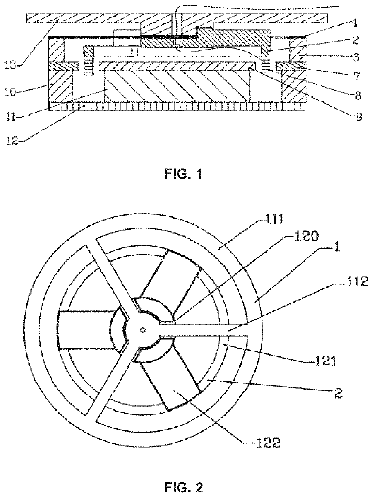
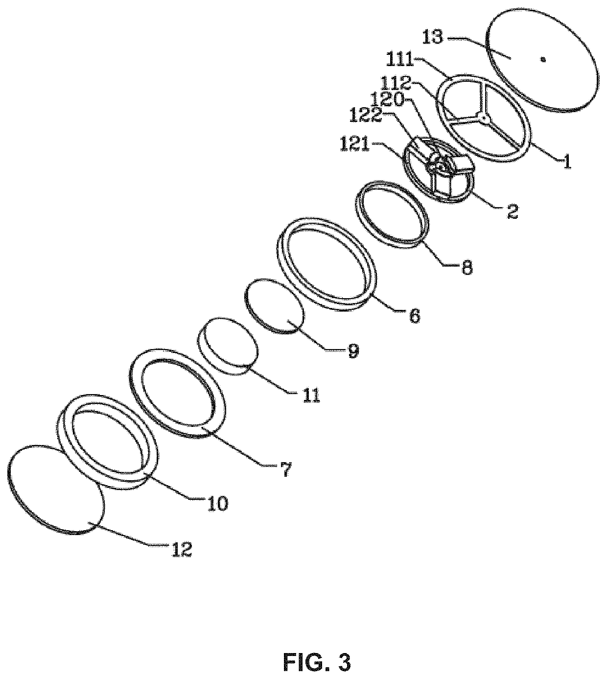
[0078]A bone conduction speaker may include a U-shaped headset bracket / headset lanyard, two vibration units, a transducer connected to each vibration unit. The vibration unit may include a contact surface and a housing. The contact surface may be an outer surface of a silicone rubber transfer layer and may be configured to have a gradient structure including a convex portion. A clamping force between the contact surface and skin due to the headset bracket / headset lanyard may be unevenly distributed on the contact surface. The sound transfer efficiency of the portion of the gradient structure may be different from the portion without the gradient structure.

example 2

[0079]This example may be different from Example 1 in the following aspects. The headset bracket / headset lanyard as described may include a memory alloy. The headset bracket / headset lanyard may match the curves of different users' heads and have a good elasticity and a better wearing comfort. The headset bracket / headset lanyard may recover to its original shape from a deformed status last for a certain period. As used herein, the certain period may refer to ten minutes, thirty minutes, one hour, two hours, five hours, or may also refer to one day, two days, ten days, one month, one year, or a longer period. The clamping force that the headset bracket / headset lanyard provides may keep stable, and may not decline gradually over time. The force intensity between the bone conduction speaker and the body surface of a user may be within an appropriate range, so as to avoid pain or clear vibration sense caused by undue force when the user wears the bone conduction speaker. Moreover, the cl...

example 3

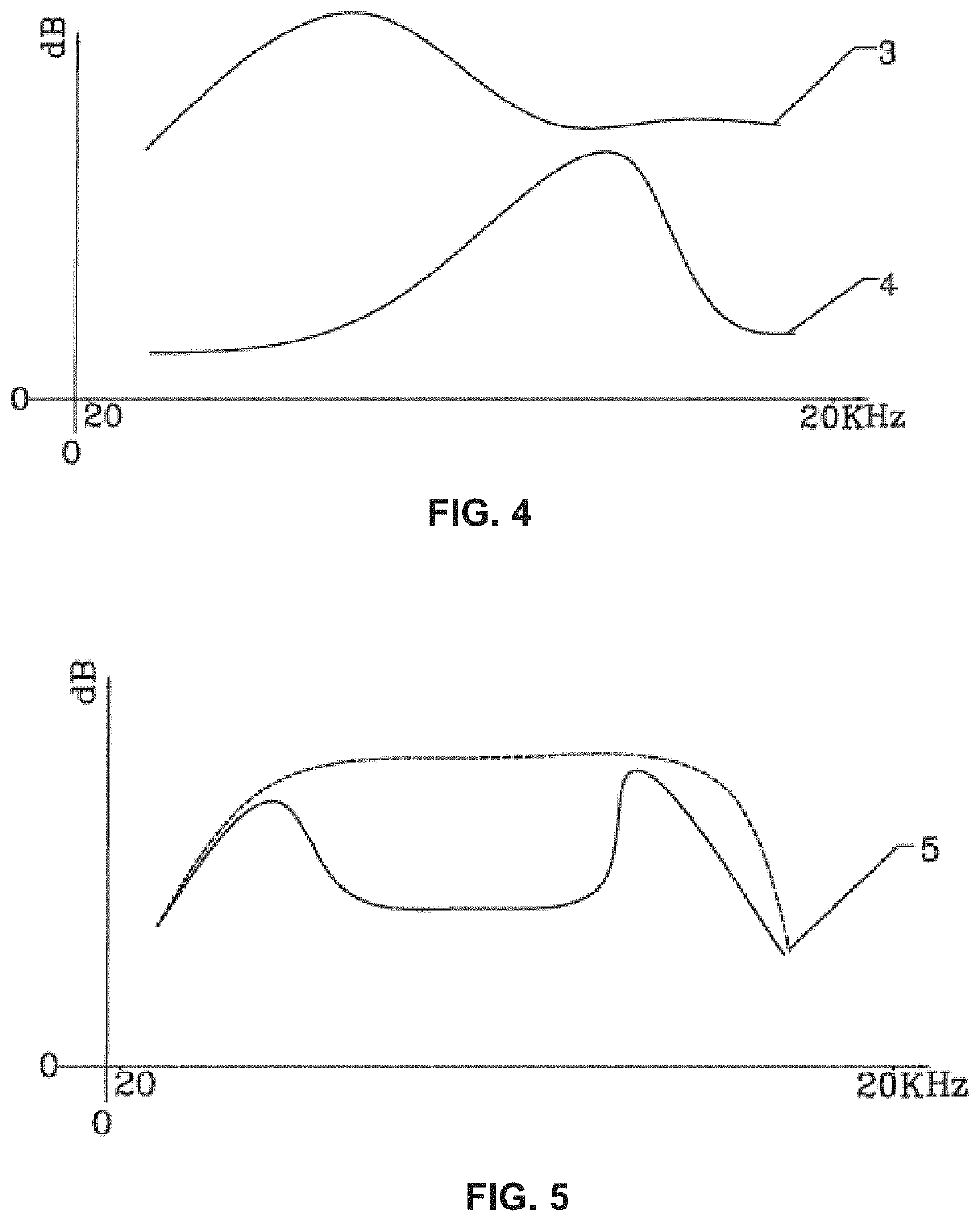
[0080]The difference between this example and the two examples mentioned above may include the following aspects. The elastic coefficient of the headset bracket / headset lanyard may be kept in a specific range, which results in the value of the frequency response curve in low frequency (e.g., under 500 Hz) being higher than the value of the frequency response curve in high frequency (e.g., above 4000 Hz).


PUM


Abstract

The present invention relates to a bone conduction speaker and its compound vibration device. The compound vibration device comprises a vibration conductive plate and a vibration board, the vibration conductive plate is set to be the first torus, where at least two first rods inside it converge to its center; the vibration board is set as the second torus, where at least two second rods inside it converge to its center. The vibration conductive plate is fixed with the vibration board; the first torus is fixed on a magnetic system, and the second torus comprises a fixed voice coil, which is driven by the magnetic system. The bone conduction speaker in the present invention and its compound vibration device adopt the fixed vibration conductive plate and vibration board, making the technique simpler with a lower cost; because the two adjustable parts in the compound vibration device can adjust both low frequency and high frequency area, the frequency response obtained is flatter and the sound is broader.

Description

CROSS-REFERENCE TO RELATED APPLICATIONS[0001]This application is a continuation-in-part application of U.S. patent application Ser. No. 17 / 161,717, filed on Jan. 29, 2021, which is a continuation-in-part application of U.S. patent application Ser. No. 16 / 159,070 (issued as U.S. Pat. No. 10,911,876), filed on Oct. 12, 2018, which is a continuation of U.S. patent application Ser. No. 15 / 197,050 (issued as U.S. Pat. No. 10,117,026), filed on Jun. 29, 2016, which is a continuation of U.S. patent application Ser. No. 14 / 513,371 (issued as U.S. Pat. No. 9,402,116), filed on Oct. 14, 2014, which is a continuation of U.S. patent application Ser. No. 13 / 719,754 (issued as U.S. Pat. No. 8,891,792), filed on Dec. 19, 2012, which claims priority to Chinese Patent Application No. 201110438083.9, filed on Dec. 23, 2011: this application and U.S. patent application Ser. No. 17 / 161,717, filed on Jan. 29, 2021 are also continuation-in-part applications of U.S. patent application Ser. No. 16 / 833,839,...

Claims


Application Information

Patent Timeline
Patent Type & Authority Applications(United States)
IPC IPC(8): H04R25/00H04R9/06
CPCH04R25/606H04R2460/13H04R9/06H04R9/066H04R1/2888H04R7/10H04R7/24
Inventor QI, XINLIAO, FENGYUNZHENG, JINBOCHEN, QIANCHEN, HAO
Owner SHENZHEN SHOKZ CO LTD
Features
  • R&D
  • Intellectual Property
  • Life Sciences
  • Materials
  • Tech Scout
  • Unparalleled Data Quality
  • Higher Quality Content
  • 60% Fewer Hallucinations
Learn More