Supercharge Your Innovation With Domain-Expert AI Agents!

Method for sequential predictive control, first solving a cost function and subsequently a second cost function for two or more control objectives

a predictive control and cost function technology, applied in the direction of adaptive control, control system, instruments, etc., can solve the problems of unstandardized control of equipment, further complicated process of selecting weight factors, and inability to standardize control

Active Publication Date: 2021-06-17
UNIV ANDRES BELLO
View PDF2 Cites 1 Cited by
  • Summary
  • Abstract
  • Description
  • Claims
  • Application Information

AI Technical Summary

Benefits of technology

The patent text is trying to find a way to minimize the cost of an objective. The technical effect of this invention is to provide a solution for controlling a system or process that reduces the cost of a specific objective.

Problems solved by technology

A problem of interest today is the control of these equipment, called inverters / rectifiers.
Today there are two major control proposals, one of them is linear control, a technology that has been in the industry for more than 60 years, however, the equipment used today is not linear systems and requires the linearization of its equations to operate at a specific point of work.
However, one of the great shortcomings of this control strategy is its implementation, because at the time of wanting to control multiple variables it requires adjusting a weight or weighting factor, whose adjustment is not standardized and requires an empirical adjustment (test / error).
Depending on the type of cost function that is obtained, a certain process of adjusting the weight factors can be carried out, for example, for the case of group 1 it is not necessary to adjust any weight factor, but for case 2 the adjustment process is not direct and an empirical adjustment is necessary through simulation checking and observation of the effect of the same, but for case 3 the process of selection of weight factors is further complicated, because it is not possible to distinguish what is the variable that is producing the final resulting effect that can be seen in the simulations performed in order to try to adjust it.

Method used


Image

  • Method for sequential predictive control, first solving a  cost function and subsequently a second cost function for two or more control objectives
  • Method for sequential predictive control, first solving a  cost function and subsequently a second cost function for two or more control objectives
  • Method for sequential predictive control, first solving a  cost function and subsequently a second cost function for two or more control objectives

Examples


application example

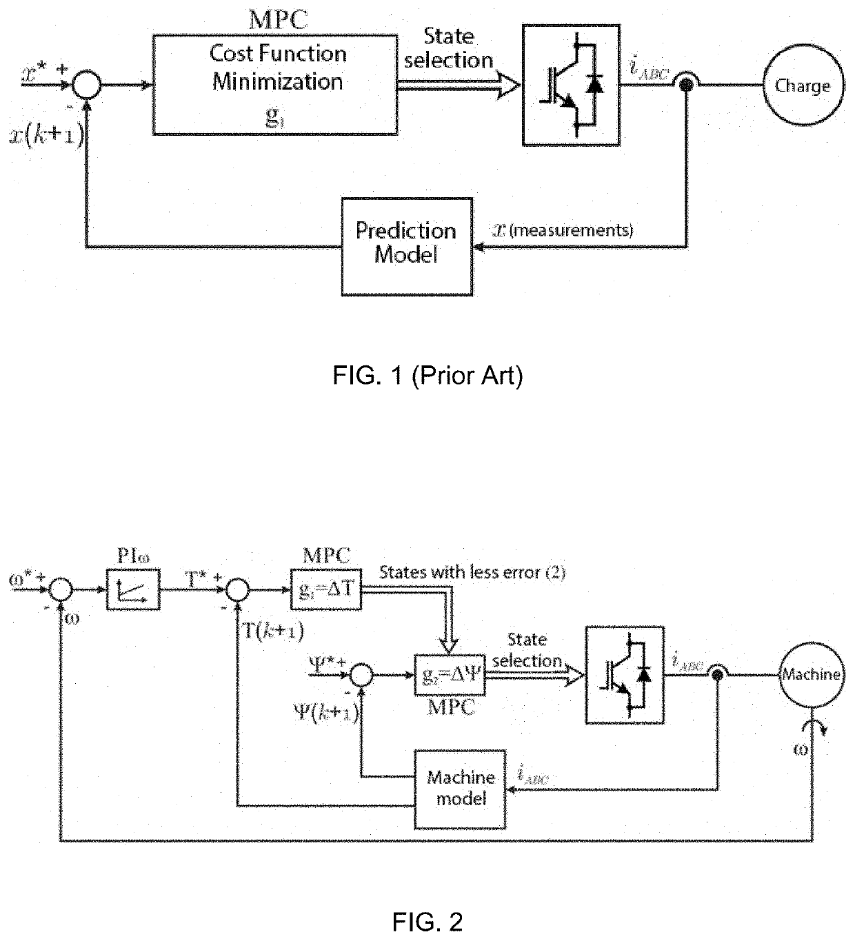
[0044]The present invention provides a method of sequential predictive control as shown in FIG. 2, where the application is for an induction machine consisting of first controlling a variable with a unitary cost function (a single term or control objective) and then the following terms. In this case of the control of an electric machine, the first variable to be controlled is the Torque, whose reference value is given, in this case, by the linear control of the angular speed of the machine. The two possible driving states of the converter that minimize the Torque are determined and then the predictive control of the Flow is carried out, which minimizes its cost function considering only the two options delivered by the Torque control process. The state that minimizes the error in the Stator Electric Flow is the one applied in the system.

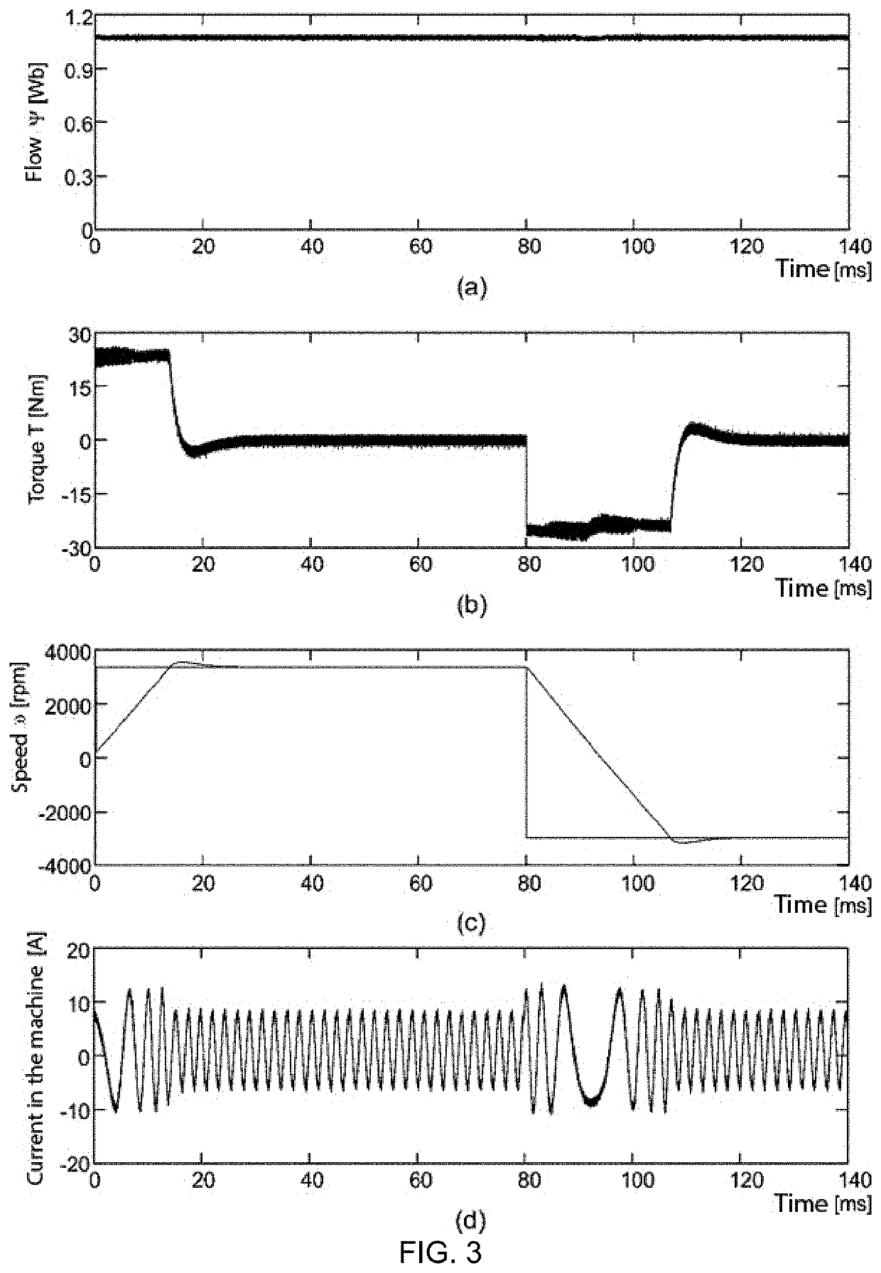
[0045]Using the method of sequential predictive control of the present invention, the control of the induction machine was performed, which presents...


PUM


Abstract

A sequential or cascading predictive control method is provided, including first solving a cost function and then a second cost function for two or more control objectives. The method includesseparating the cost function into at least two or more cost functions, depending on the number of defined control objectives.The method additionally includes controlling a first variable with a unitary cost function, a single term or nature of the control objectives.The method also includes determining the possible states that minimize the cost of the first objective to be controlled.Considering only the options given through this determination, a second variable is controlled with a cost function that minimizes the cost function thereof.

Description

APPLICATION FIELD[0001]The present invention relates to the control of equipment or system processes, more specifically to a predictive control method, and more specifically a sequential or cascade predictive control method, first solving a cost function and then a second cost function for Two or more control objectives.DESCRIPTION OF THE PRIOR ART[0002]In our today society, electricity is a fundamental pillar in the various activities carried out day by day. The use and transport of electric energy is carried out using strategic equipment based on power semiconductors. A problem of interest today is the control of these equipment, called inverters / rectifiers.[0003]Today there are two major control proposals, one of them is linear control, a technology that has been in the industry for more than 60 years, however, the equipment used today is not linear systems and requires the linearization of its equations to operate at a specific point of work. In addition, this control strategy r...

Claims


Application Information

Patent Timeline
IPC IPC(8): G05B13/04H02P23/14H02P27/06
CPCG05B13/048H02P27/06H02P23/14
Inventor NORAMBUENA VALDIVIA, MARGARITARODRIGUEZ PEREZ, JOSE
Owner UNIV ANDRES BELLO
Features
  • R&D
  • Intellectual Property
  • Life Sciences
  • Materials
  • Tech Scout
  • Unparalleled Data Quality
  • Higher Quality Content
  • 60% Fewer Hallucinations
Learn More