This helps you quickly interpret patents by identifying the three key elements:
Problems solved by technology
Method used
Benefits of technology
Benefits of technology
The patent describes a baling press that can quickly press materials into a compact bale. The press also has a strapping device that uses flexible strapping material to tightly secure the bale before it is removed from the press. This helps prevent the bale from re-enlarging or falling apart.
Problems solved by technology
However, such a conveyor requires a lot of floor space in addition to the rest of the vertical box baler, whose principal advantage is that it requires very little floor space, thus losing its main advantage.
In addition, a vertically operating box baler equipped with such a conveyor cannot be placed at a small distance in front of a wall.
Method used
Image
Click on the blue label to locate the original text in one second.
Reading with bidirectional positioning of images and text.
Examples
first embodiment
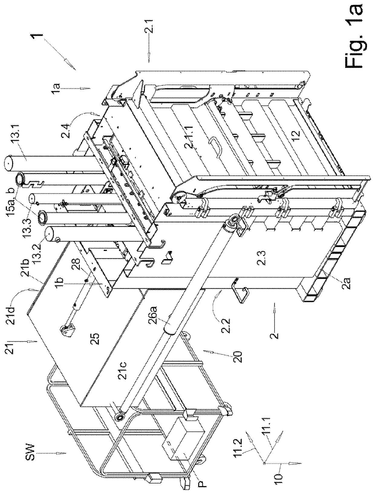
[0095]FIG. 1a: a baler according to the invention in perspective view,
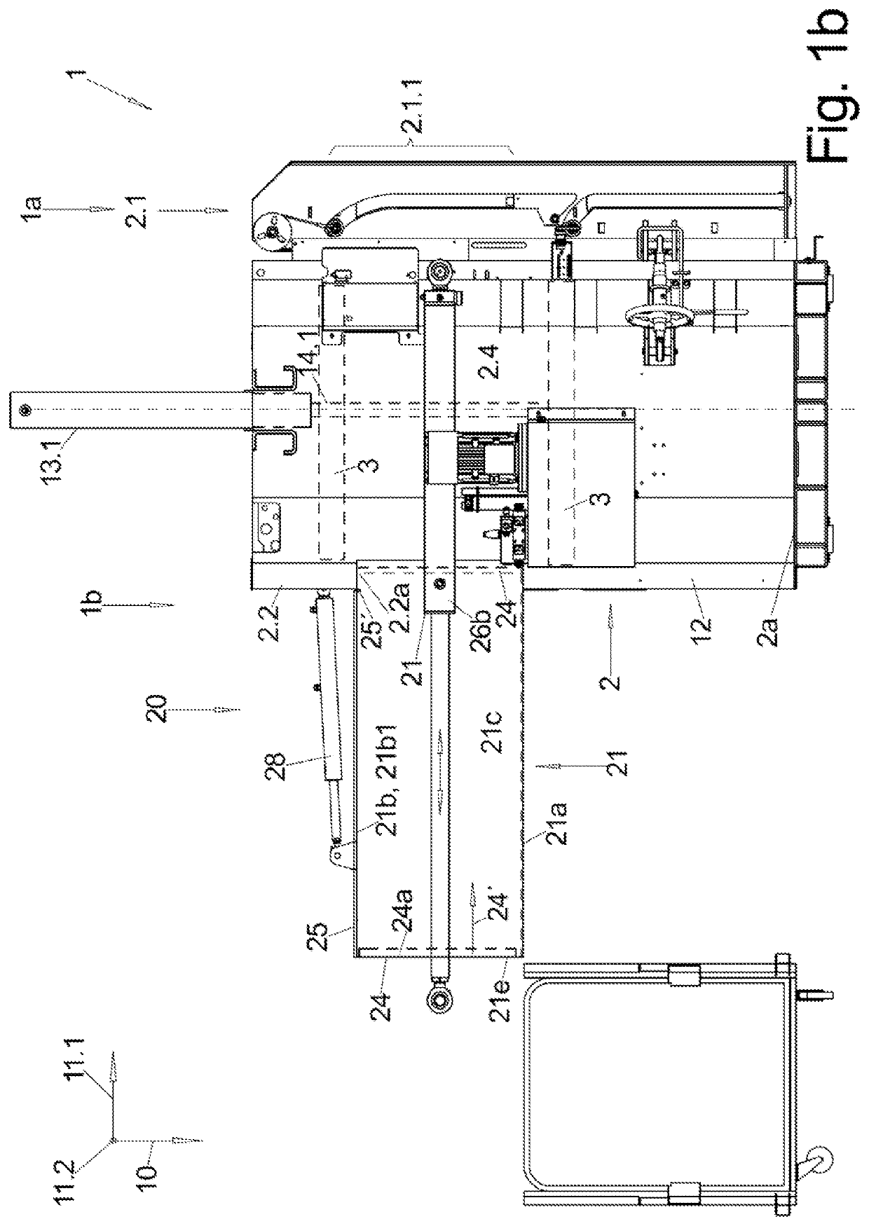
[0096]FIG. 1b: the baler of figure 1a in side view,
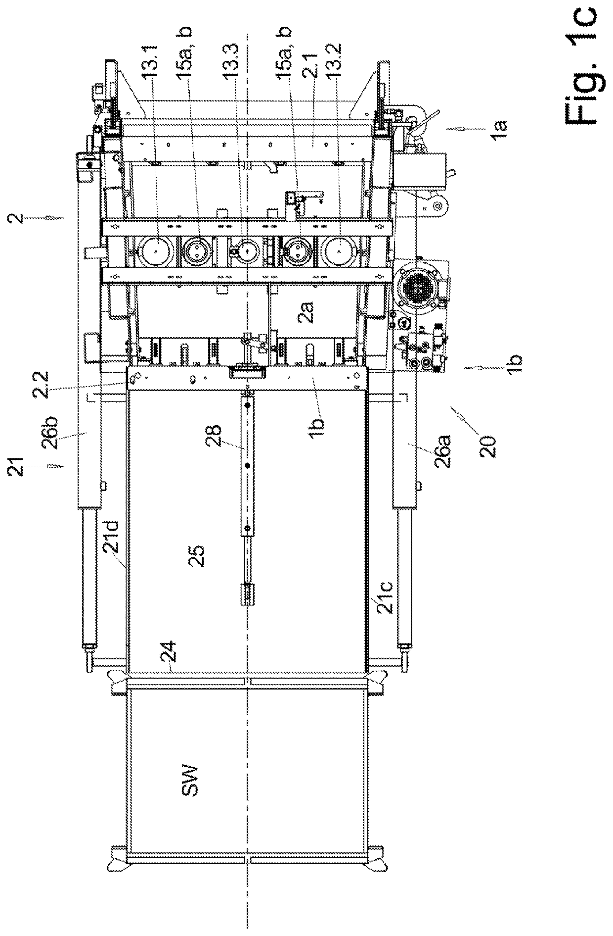
[0097]FIG. 1c: the baler according to figure 1a in top view with the cover flap of the storage container closed,
[0098]FIG. 2a: the baler of FIG. 1 while filling the storage container, but with the removal door open, in perspective view,
[0099]FIG. 2b: the baler as shown in FIG. 2a, but with the removal door closed, in side view,
[0100]FIG. 2c: the baler as shown in FIG. 2b, viewed from above,
second embodiment
[0101]FIG. 3a-c: a baler according to the invention in side view, top view and front view.
[0102]FIGS. 1a-c as well as 2a-c show a first embodiment of the inventive box baler 1 as well as a collecting trolley SW, in which material Pto be pressed such as empty cardboard boxes are collected for feeding this baler 1, but in FIG. 1 on the one hand and FIG. 2 on the other hand in two different operating situations.
[0103]In the FIGS. , the box baler 1 points with its front side 1a to the right and with its rear side 1b to the left.
[0104]A standard vertical boxe baler comprises—and these elements are also present in the baler according to the invention—a press box 2 with a bottom 2a, which in this case has a roughly rectangular shape when viewed from above, so that a total of four side walls 2.1 to 2.4 project upwards from its outer area, namely a front wall 2.1, a rear wall 2.2 opposite thereto, and longitudinal walls 2.3, 2.4 connecting these two walls to one another, so that the inner su...
PUM
Abstract
In order to be able to attach an automatic rear-end filling device (20) to a vertically operating box baler (1), which does not increase the height requirement for such an automated vertical box baler (1) too much and at the same time permits batchwise operation, a collecting trolley (SW) filled with loose material (P) is automatically lifted by means of a corresponding lifting / pivoting device (20) and dumped in a storage container (21) at the e.g. rear wall and from there it is pushed diagonally upwards in the direction of movement (24′) through a filling opening (2.2a) into the interior of the press box (2) by means of a storage pusher (24).
Description
I. FIELD OF APPLICATION[0001]The invention relates to box balers, in which the material to be pressed is pressed by a press stamp against a fixed abutment, namely the end wall of the press box. The invention relates specifically to vertically acting box balers, in which the press stamp moves up and down, usually vertically, and presses the material to be pressed against the bottom of the press box, which is open at the top and only closed by the press stamp.II. TECHNICAL BACKGROUND[0002]The one or both parallel acting press stamps are mostly actuated by hydraulic cylinders.[0003]Such vertically acting box balers are often used when the amount of material to be baled is low.[0004]Filling and emptying is often carried out from the front side of the baler, which has a closable filling opening in the upper part of its front wall, through which the loose material to be pressed—e.g. empty cartons or empty plastic bottles or beverage cans—is manually filled into the press box when the pres...
Claims
Application Information
Patent Timeline
Application Date:The date an application was filed.
Publication Date:The date a patent or application was officially published.
First Publication Date:The earliest publication date of a patent with the same application number.
Issue Date:Publication date of the patent grant document.
PCT Entry Date:The Entry date of PCT National Phase.
Estimated Expiry Date:The statutory expiry date of a patent right according to the Patent Law, and it is the longest term of protection that the patent right can achieve without the termination of the patent right due to other reasons(Term extension factor has been taken into account ).
Invalid Date:Actual expiry date is based on effective date or publication date of legal transaction data of invalid patent.

