Hinge for the rotatable movement of a door or similar closing element

Active Publication Date: 2021-06-24
COLCOM GRP SPA
View PDF0 Cites 1 Cited by
  • Summary
  • Abstract
  • Description
  • Claims
  • Application Information

AI Technical Summary

Benefits of technology

[0009]An object of the present invention is to at least partly overcome the aforem

Problems solved by technology

Known in the technical field is the difficulty to obtain holes small enough to allow an efficient control of the flow and thus the displacement of the

Method used


Image

  • Hinge for the rotatable movement of a door or similar closing element
  • Hinge for the rotatable movement of a door or similar closing element
  • Hinge for the rotatable movement of a door or similar closing element

Examples


Example

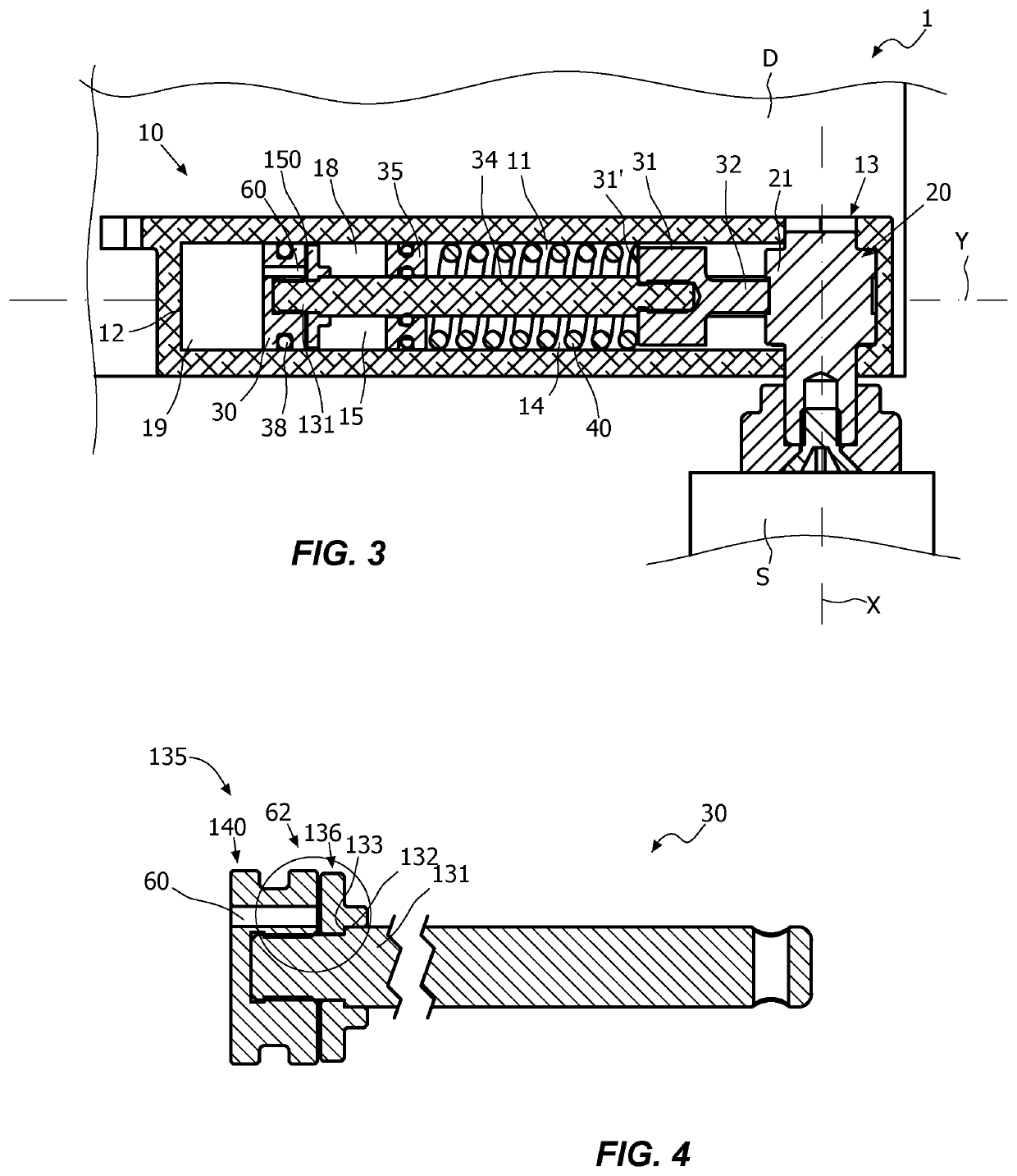
[0023]With reference to the aforementioned figures, the hinge according to the invention, indicated in its entirety with reference number 1, may be advantageously used for glass doors or shutters, such as for example those of a display window or display case.

[0024]Generally, the hinge 1 may be suitable to rotatably couple a stationary support structure, for example a frame S, and a closing element, for example a shutter D, rotatably movable between an opening and a closing position around a rotation axis X.

[0025]It is clear that even though hereinafter reference shall be made to the frame S and the shutter D, the hinge 1 is applicable to any stationary support structure and to any closing element without departing from the scope of protection of the attached claims.

[0026]The hinge 1 shall suitably include a substantially box-shaped hinge body 10 and a pivot 20 defining the rotation axis X.

[0027]In a preferred but non-exclusive embodiment, the hinge body 10 may be anchored to the shu...


PUM


Abstract

A hinge for the rotatable movement of a door or a similar closing element anchored to a wall or to a similar stationary support includes a fixed element adapted to be coupled to the wall or similar stationary support and a movable element adapted to be coupled to the door or similar closing element. The fixed and movable elements are coupled to mutually rotate around a first longitudinal axis between an open position and a closed position. The hinge further includes a hydraulic duct with a calibrated passage for s working fluid and an adjustment system acting thereon to control the movement of the door or similar closing element.

Description

FIELD OF THE INVENTION[0001]The present invention generally regards the technical field of closing or control hinges, and it particularly regards a hinge for the rotatable movement of a door, a shutter or the like.STATE OF THE ART[0002]Hinges comprising a hinge body and a pivot mutually coupled to allow a closing element, such as a door, a shutter or the like, to rotate between an open position and a closed position, are known.[0003]In particular, known are hydraulic hinges comprising a plunger element having a slidable disc-shaped head suitable to partition the working chamber into two variable volume compartments.[0004]Thus, known is the need to provide one or more hydraulic ducts to place in fluid communication such variable volume compartments so as to allow the sliding of the plunger element.[0005]As known, the dimension of such hydraulic ducts and in particular of the through-flow openings determines the flow of the liquid passing from one compartment to the other and thus the...

Claims


Application Information

Patent Timeline
IPC IPC(8): E05F3/20E05F3/10
CPCE05F3/20E05F3/104E05Y2900/132E05Y2201/638E05Y2900/146E05F3/12
Inventor BENEDETTI, LUCAMESAROS, MIHAI
Owner COLCOM GRP SPA
Why Eureka
Try Eureka