Coil spring

a coil spring and coil technology, applied in the field of coil springs, can solve the problems of deterioration of the rigidity of the first and second end coil parts, increase of wear and frictional heat, etc., and achieve the effect of preventing the deterioration of the rigidity of the end portion

Active Publication Date: 2021-06-24
SANCALL +1
View PDF0 Cites 3 Cited by
  • Summary
  • Abstract
  • Description
  • Claims
  • Application Information

AI Technical Summary

Benefits of technology

[0018]The present invention has been conceived in view of such conventional art, and an object of the present invention is to provide a coil spring cap

Problems solved by technology

An increased frictional force leads to increased wear and frictional heat due to sliding resistance to the plunger, and may result in operational problems of an apparatus such as a high-pressure pump where the plunger is used.
However, if

Method used


Image

  • Coil spring
  • Coil spring
  • Coil spring

Examples


Embodiment Construction

[0039]Below, one embodiment of the coil spring according to the present invention will now be described with reference to the attached drawings.

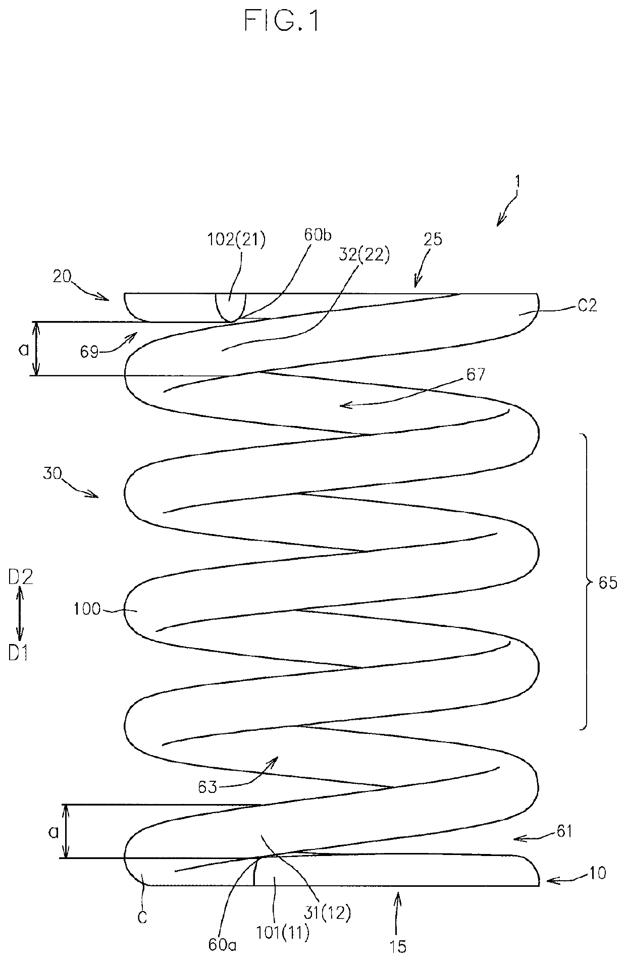
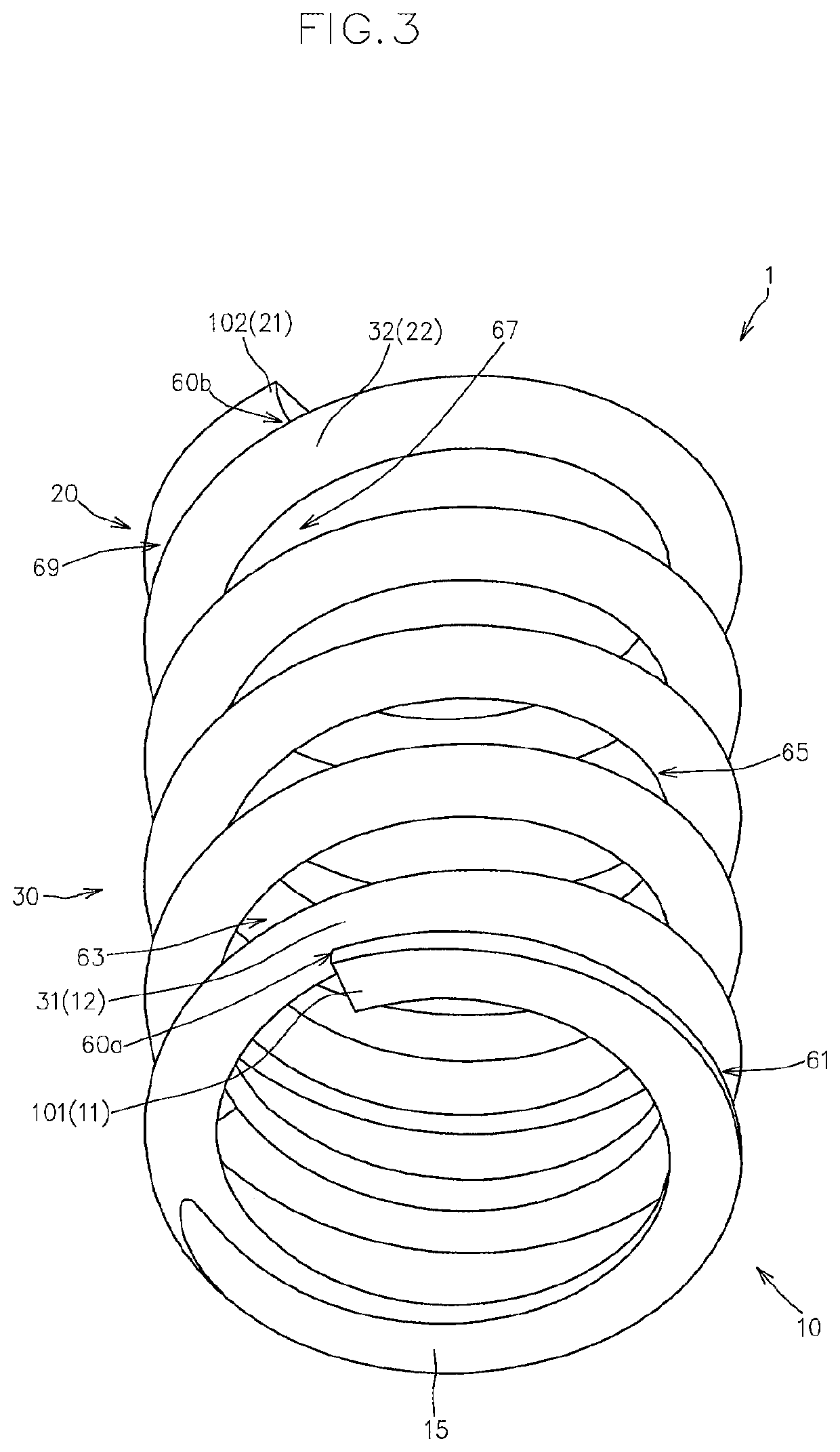
[0040]FIGS. 1 to 5 show a front view, an upper perspective view, a lower perspective view, plan view and a bottom view, respectively, of a coil spring 1 according to the present embodiment in a natural length state.

[0041]As shown in FIGS. 1 to 5, the coil spring 1 according to the present embodiment is obtained by forming a spring wire 100 into a helical shape axially extending from a first end portion 101 on a first side D1, which is one side in the axial direction, to a second end portion 102 on a second side D2, which is the other side in the axial direction, and is suitably used as a valve spring for an internal combustion engine, a spring for a high-pressure pump, and the like.

[0042]Although, in the coil spring 1 according to the present embodiment, the spring wire 100 has a circular cross section, it is possible to use spring wires hav...


PUM


Abstract

A coil spring of this invention includes a first end coil part with a first bearing surface facing to the first side in the axial direction, a second end coil part with a second bearing surface facing to the second side in the axial direction and a central coil part connecting the first and second end coil parts. A displacement length in the axial direction from the outer end portion until the inner end portion of the first end coil part is a thickness of a spring wire forming the coil spring so that a space between the outer end portion of the first end coil part and an inner end portion of the central coil part is zero, and a displacement length in the axial direction between the outer end portion of the first end coil part and a point away along the circumferential direction from the outer end portion toward the inner end portion of the first end coil part by a half of turn around the axial line is less than a half of the thickness of the spring wire.

Description

FIELD OF THE INVENTION[0001]The present invention relates to a coil spring available for a valve spring for an internal combustion engine, a spring for a high-pressure pump, and the like.BACKGROUND ART[0002]A coil spring obtained by forming a spring wire into a helical shape that axially extends from one side toward the other side is widely used as a valve spring for an internal combustion engine, a spring for a high-pressure pump, and the like.[0003]This coil spring is a component intended to axially exert elastic force when axially compressed, and is known to also produce, in addition to the elastic force in the axial direction, force (lateral force) in the direction perpendicular to the axial direction when compressed.[0004]Desirably, production of lateral force is prevented as much as possible.[0005]That is to say, for example, when lateral force is produced in the case of using the coil spring as a pressing member for pressing a reciprocating plunger, frictional force produced ...

Claims


Application Information

Patent Timeline
IPC IPC(8): F16F1/06F16F1/04
CPCF16F1/06F16F1/042F01L2303/01F16F1/047F01L1/462F01L2820/01F01L2820/02
Inventor KISHIHARA, RYUJIOKAMURA, SEIJI
Owner SANCALL
Why Eureka
Try Eureka