Baling apparatus

Pending Publication Date: 2021-07-01
AGCO CORP
View PDF0 Cites 0 Cited by
  • Summary
  • Abstract
  • Description
  • Claims
  • Application Information

AI Technical Summary

Benefits of technology

[0011]This has as an advantage that it allows the improving of the mechanical advantage at the tractor PTO through the addition of a lower ratio (speed) range

Problems solved by technology

Conversely, flywheels are limited in size, due to the ability to, means or process for accelerating the flywheel to a desired operating

Method used


Image

  • Baling apparatus
  • Baling apparatus
  • Baling apparatus

Examples


Embodiment Construction

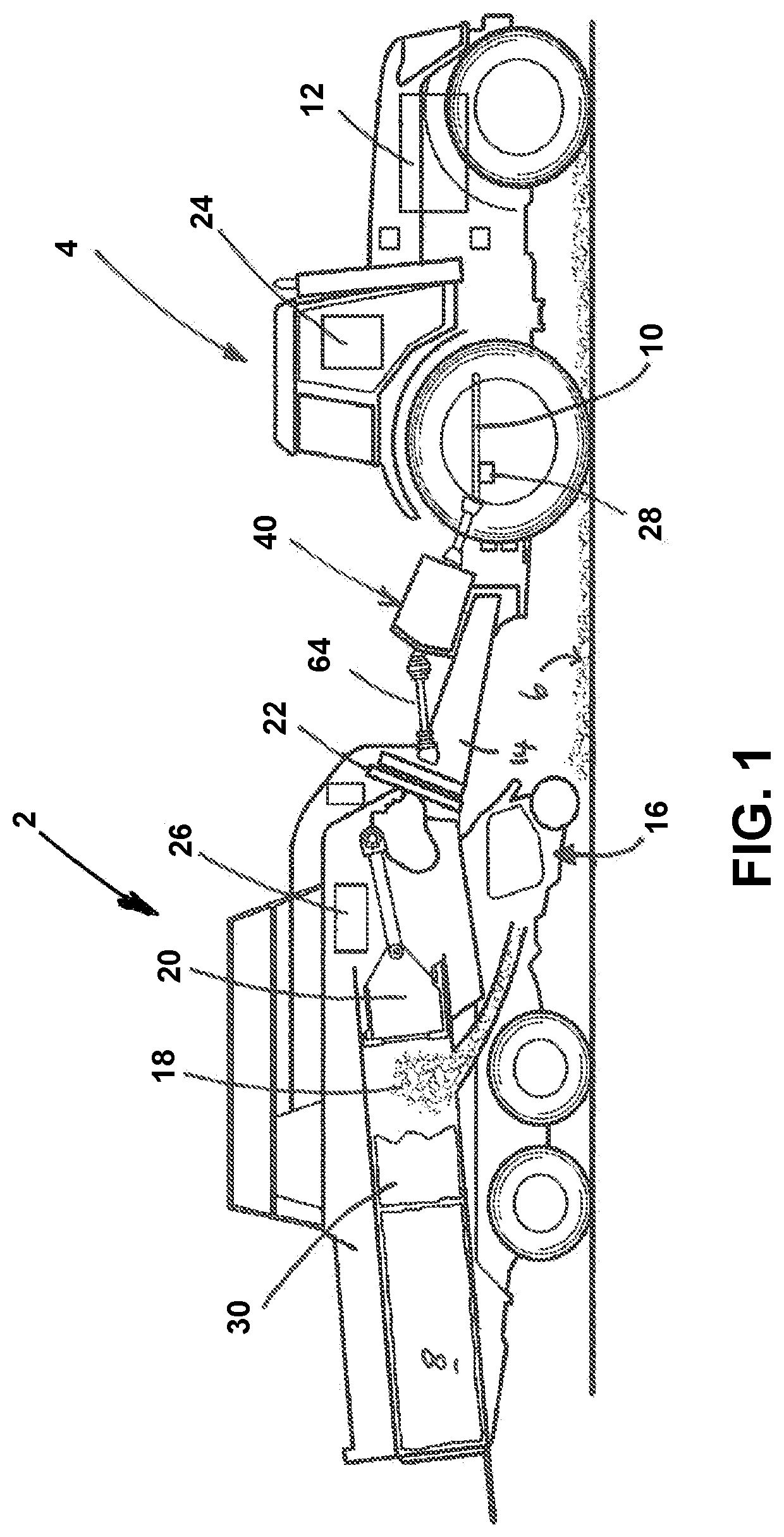
[0032]The invention will now be described in the following detailed description with reference to the drawings, wherein preferred embodiments are described in detail to enable practice of the invention. Although the invention is described with reference to these specific preferred embodiments, it will be understood that the invention is not limited to these preferred embodiments. But to the contrary, the invention includes numerous alternatives, modifications and equivalents as will become apparent from consideration of the following detailed description.

[0033]Reference to terms such as longitudinal, transverse and vertical are made with respect to a longitudinal vehicle axis which is parallel to a normal forward direction of travel.

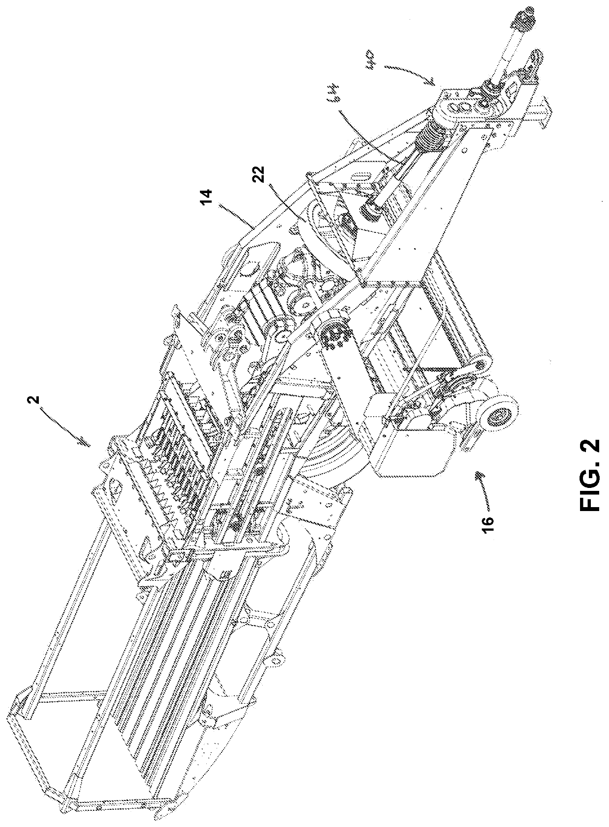
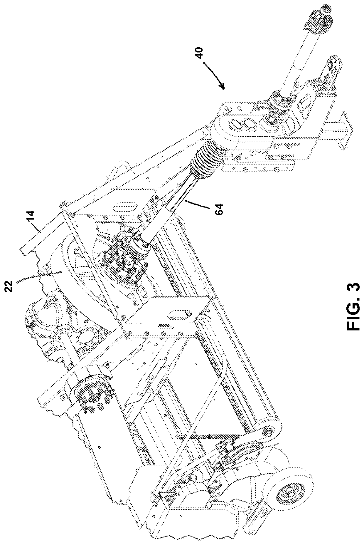
[0034]With reference to FIG. 1, a schematic side view of an agricultural vehicle connected to an agricultural implement by a connector in accordance with the present invention is shown. Reference should also be made to FIGS. 2 and 3. A baler 2 is, in use...


PUM


Abstract

A baler including a flywheel driven by a PTO of a tractor, an input shaft which connects to the PTO, an output shaft which connects to the flywheel, an intermediate gear mounted for rotation between the input shaft and the output shaft, the intermediate gear being parallel to the input shaft and adapted to drive the output shaft, wherein the input shaft includes a displaceable geared collar adapted to engage the intermediate gear with either a first lower gear ratio or a second higher gear ratio. This allows the tractor PTO a lower ratio (speed) range to start the flywheel and then accelerate the flywheel to an intermediate speed before shifting and accelerating to the final desired operating speed.

Description

CROSS REFERENCE TO RELATED APPLICATION[0001]This application claims the benefit of U.S. Provisional Application No. 62 / 955,680, filed Dec. 31, 2019, which is hereby incorporated by reference in its entirety.BACKGROUNDField[0002]The present invention relates to a baling apparatus and in particular to a baling apparatus for producing square bales.Description of Related Art[0003]It is known to construct a baling apparatus for square bales in which a plunger reciprocates in a baling chamber. As crop material is introduced into the baling chamber, the plunger slides into the baling chamber to compress the crop material into a bale. The plunger is typically driven by a Power Take Off (PTO) system of a towing vehicle, such as a tractor, while the tractor is driven along a field.[0004]In practice large square balers use a flywheel having a high inertial mass to store and release energy during the above cyclic loading cycle of the baling operation. Generally flywheels have become larger in s...

Claims


Application Information

Patent Timeline
IPC IPC(8): A01F15/08B30B9/30F16H3/32
CPCA01F15/0841B30B9/306A01F15/04F16H3/32B30B9/3007
Inventor WILLIAMS, NICHOLAS H.
Owner AGCO CORP
Why Eureka
Try Eureka