Vehicle cleaning system
a technology for cleaning systems and vehicles, applied in vehicle cleaning, electric/fluid circuits, vehicle components, etc., can solve problems such as the detection performance of these onboard sensors may suffer, and achieve the reduction of cleaning liquid consumption, deterioration of optical sensor detection performance, and suppression of vehicle cleaning liquid consumption.
- Summary
- Abstract
- Description
- Claims
- Application Information
AI Technical Summary
Benefits of technology
Problems solved by technology
Method used
Image
Examples
first exemplary embodiment
[0065]Detailed explanation follows regarding a vehicle cleaning system according to a first exemplary embodiment of the present disclosure, with reference to the drawings. The exemplary embodiment described below uses the example of a vehicle with an autonomous driving system as one example of a specific implementation of the technical concept of the present disclosure, and is not intended to limit the present disclosure to this embodiment. The present disclosure may equally be applied to a vehicle cleaning system of a vehicle provided with cleaning targets such as an optical sensor even in cases in which an autonomous driving system is not provided.
[0066]Explanation will first be given regarding autonomous driving levels in order to assist understanding of the present disclosure. Autonomous driving is classified into the following levels, as defined in SAE J3016 of SAE international (a U.S. non-profit organization for mobility experts).
Level 0: No driving automation
Level 1: Driving...
second exemplary embodiment
[0194]Explanation follows regarding a second exemplary embodiment of the present disclosure. Note that sections configured similarly to those of the first exemplary embodiment are allocated the same reference numerals, and explanation thereof is omitted.
[0195]In the vehicle 210 installed with the vehicle cleaning system 1, since cleaning of the cleaning targets such as the optical sensors is performed without the driver knowing, cleaning liquid may be consumed faster than the driver is aware, which may result in a cleaning liquid shortage. The second exemplary embodiment is provided with a mechanism to inform the driver of the remaining cleaning liquid level based on detection values of the level sensor 13 provided to the washer tank 12. This allows the driver to check the remaining cleaning liquid level at any time.
[0196]The vehicle 210 of the second exemplary embodiment is provided with a remaining level display section 235 (see FIG. 4A to FIG. 4C) to display the remaining cleanin...
third exemplary embodiment
[0222]Explanation follows regarding a third exemplary embodiment of the present disclosure. Note that sections configured similarly to those of the first exemplary embodiment are allocated the same reference numerals, and explanation thereof is omitted.
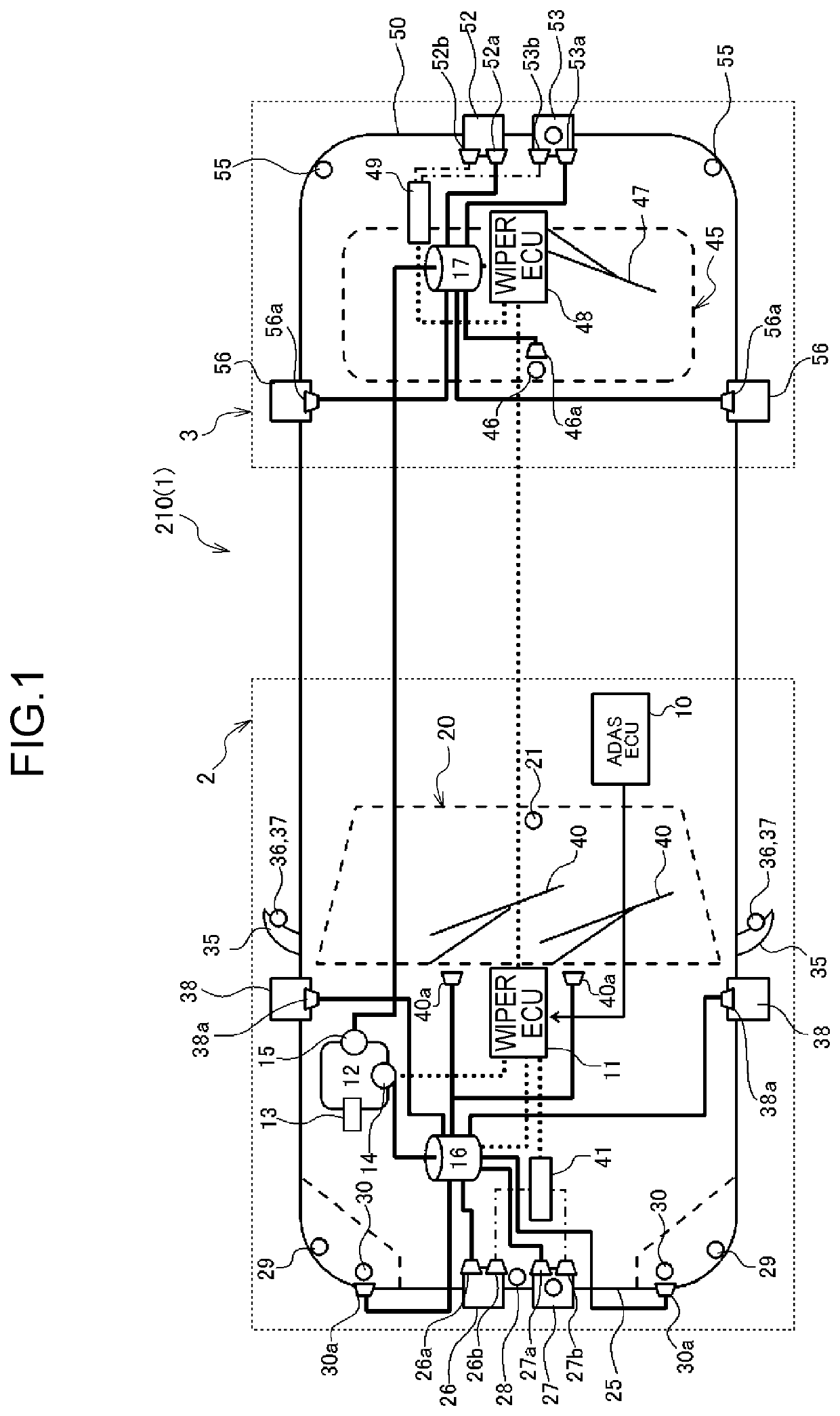
[0223]Configuration of a vehicle cleaning system 1 of a vehicle 210 according to the third exemplary embodiment is similar to that of the first exemplary embodiment. In the vehicle cleaning system 1 of the third exemplary embodiment, the front wiper ECU 11 and the rear wiper ECU 48 are provided independently of the ADAS-ECU 10. Explanation follows from the perspectives of control of the cleaning sections corresponding to the front control section 2 by the front wiper ECU 11, and control of the cleaning sections corresponding to the rear control section 3 by the rear wiper ECU 48.
[0224]FIG. 7 illustrates a comparative example in order to explain operation of the third exemplary embodiment. Explanation follows regarding the comparative ...
PUM
 Abstract
Description
Claims
Application Information
 - R&D
- Intellectual Property
- Life Sciences
- Materials
- Tech Scout
- Unparalleled Data Quality
- Higher Quality Content
- 60% Fewer Hallucinations
Browse by: Latest US Patents, China's latest patents, Technical Efficacy Thesaurus, Application Domain, Technology Topic, Popular Technical Reports.
© 2025 PatSnap. All rights reserved.Legal|Privacy policy|Modern Slavery Act Transparency Statement|Sitemap|About US| Contact US: help@patsnap.com


