Transmission for a Motor Vehicle

Inactive Publication Date: 2021-07-08
ZF FRIEDRICHSHAFEN AG
View PDF0 Cites 0 Cited by
  • Summary
  • Abstract
  • Description
  • Claims
  • Application Information

AI Technical Summary

Benefits of technology

The invention is about a motor vehicle transmission that includes an electric machine or motor. The transmission has a compact design and low drag losses because of a highly-loaded shift element in the first forward gear. Additionally, the shift element can be engaged under load in a traction downshift. The shift element is positioned directly on the housing of the transmission and is lubricated with oil. This oil feed is facilitated by an oil feed system located on the edge of the housing, which allows for a compact transmission design. The technical effects of this invention include improved performance and efficiency of the motor vehicle transmission.

Problems solved by technology

However, this increases the design complexity of the transmission as well as its outer dimensions, and results in elevated drag torques.
This restricts the power shiftability of the transmission.
If the shift element to be engaged only in the first forward gear is designed as a form-fit shift element, such a coasting downshift cannot be carried out under load without special measures.
Remaining in the second forward gear during coasting results in frequent traction downshifts from the second forward gear into the first forward gear, however, for example when the motor vehicle is to be accelerated again from a slowly rolling condition.
In the case of an engaging form-fit shift element, such a gear change operation can result in a worsening of the shifting comfort
However, this patent application provides no guidelines for making a selection in the case of highly loaded shift elements which are to be engaged in traction downshifts.

Method used


Image

  • Transmission for a Motor Vehicle
  • Transmission for a Motor Vehicle
  • Transmission for a Motor Vehicle

Examples


Embodiment Construction

[0029]Reference will now be made to embodiments of the invention, one or more examples of which are shown in the drawings. Each embodiment is provided by way of explanation of the invention, and not as a limitation of the invention. For example, features illustrated or described as part of one embodiment can be combined with another embodiment to yield still another embodiment. It is intended that the present invention include these and other modifications and variations to the embodiments described herein.

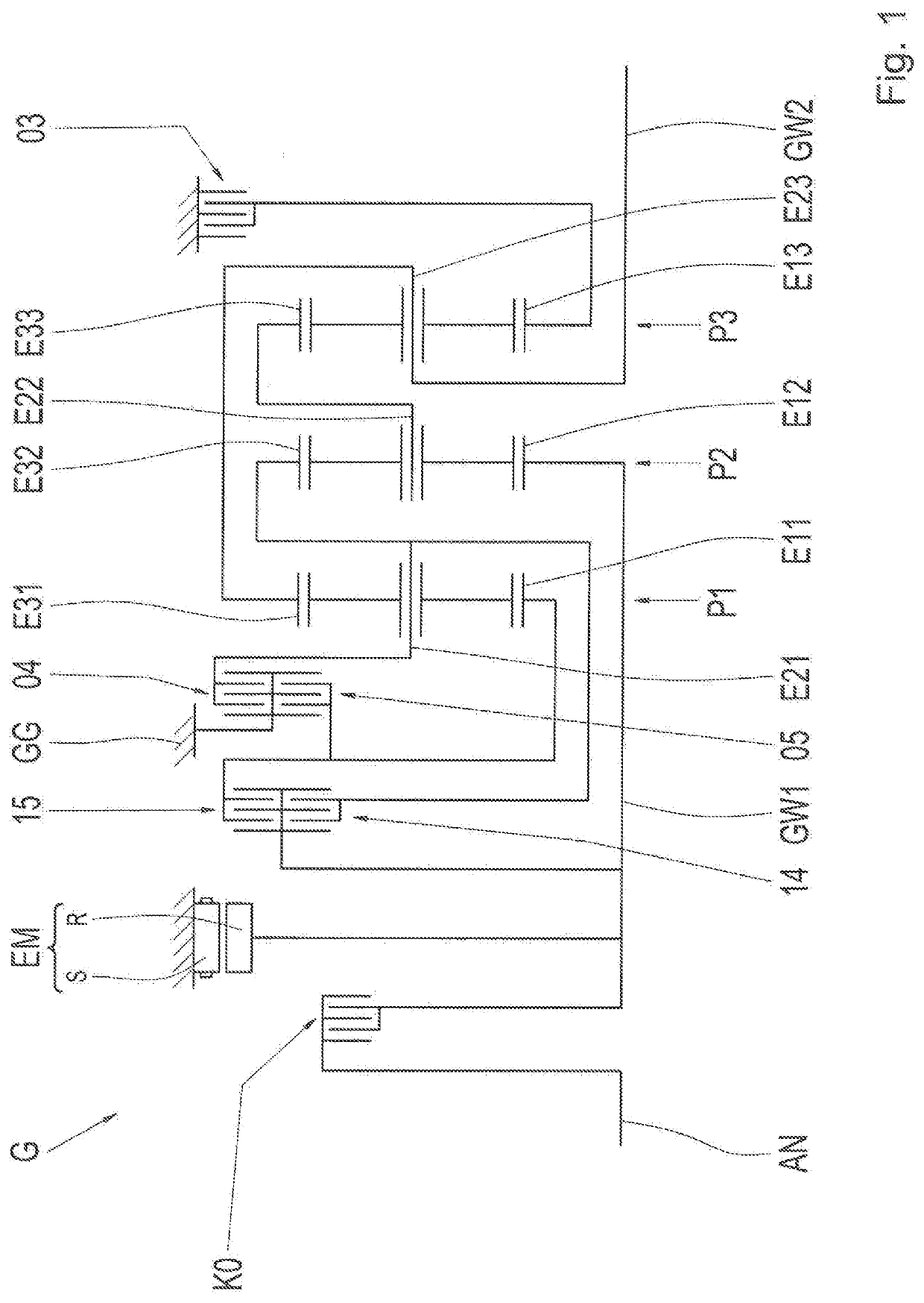
[0030]FIG. 1 schematically shows a transmission G according to one exemplary embodiment of the invention. The transmission G includes a first planetary gear set P1, a second planetary gear set P2, a third planetary gear set P3, an input shaft GW1, an output shaft GW2, an electric machine or motor EM including a rotationally fixed stator S and a rotary rotor R, as well as a first shift element 04, a second shift element 05, a third shift element 03, a fourth shift element 14, and a...


PUM


Abstract

A transmission (G) for a motor vehicle includes an input shaft (GW1), an output shaft (GW2), an electric motor (EM) which is configured for driving the input shaft (GW1) and is operable as a generator, a plurality of planetary gear sets (P1, P2, P3), and a plurality of shift elements (03, 04, 05, 14, 15). By selectively engaging the shift elements (03, 04, 05, 14, 15), various forward gears (1 to 6) between the input shaft (GW1) and the output shaft (GW2) are formable. A first shift element (04) contributes only to forming the first of the forward gears (1 to 6). By engaging the first shift element (04), a carrier (E21) of one of the planetary gear sets (P1, P2, P3) is rotationally fixable. The first shift element (04) is a friction-locking frictional shift element, friction faces of which have no friction lining and have the same surface property.

Description

FIELD OF THE INVENTION[0001]The invention relates generally to a transmission for a motor vehicle.BACKGROUND[0002]Patent application US 2012 / 0178573 A1 describes a transmission including an input element, an output element, three planetary gear sets, and a plurality of torque transmission units. The input element is connected to an input shaft of the transmission via a damper and a clutch. An electric motor is connected to the input shaft. The gear set structure on which this transmission is based is described in patent application DE 199 12 480 A1.[0003]The shortest forward ratio which can be obtained with this transmission can be obtained by engaging the torque transmission units marked as 68 and 66. In the case of a high input-shaft torque, the torque transmission unit marked as 66 undergoes a high torque load. When the torque transmission unit marked as 66 is designed as a lamellar shift element which is usual in automatic transmissions and is formed from disks including frictio...

Claims


Application Information

Patent Timeline
IPC IPC(8): F16H3/66B60K6/365
CPCF16H3/66B60K6/48B60K6/365B60K2006/4825F16H57/10F16H2200/0052F16H2200/201F16H2200/2043Y02T10/62
Inventor BECK, STEFANBREHMER, MARTINHORN, MATTHIASFÜHRER, KIMGEIGER, ANDREASRIEDISSER, THOMAS
Owner ZF FRIEDRICHSHAFEN AG
Why Eureka
Try Eureka