Gramophone plate with recorded image

a gramophone plate and image technology, applied in the field of gramophone plates, can solve the problems of insufficient width, too small for the formation of an image recording therein, and the limitations of known technologies, so as to prevent the recording of additional audio noise, reduce or mitigate the effect of this

Pending Publication Date: 2021-07-08
IQ STRUCTURES SRO
View PDF41 Cites 0 Cited by
  • Summary
  • Abstract
  • Description
  • Claims
  • Application Information

AI Technical Summary

Benefits of technology

[0055]Using the above technology, it may be possible for the optical relief of the visual image(s)/image portion(s) to be applied so as to cover or extend over substantially the whole surface width or width region/area between adjacent audio log lines, i.e. substantially right up to the edges of audio log lines. Therefore, it may be desirable for the edges of audio log lines actually at the surface plane of the plate to be not exactly in-plane with the plate's surface plane, because of possible interference with the optical relief recording the visual image(s)/image portion(s), which could

Problems solved by technology

The principle of recording a visual image onto or into the surface of a gramophone plate by varying the surface relief of the plate material is well-known, but conventionally it has always been limited by the need for the area of the plate carrying the image to be separate from the area carrying the audio data record.
Firstly, there are practical limitations of known technologies used for the actual recording of audio data on gramophone plates. This known technology is generally based on the mechanical cutting of an audio data log line into the recording medium by means of various electro-mechanical cutting devices, which are structurally highly specialized and designed solely for audio data recording whilst maintaining or optimizing required levels of quality of the audio data recorded. The cutting of data log lines is strictly linear and carried out without stopping or interrupting the cut process, and is carried out under force and speed conditions dependent on the recording medium, e.g. typically a lacquer layer or a copper layer, and so as to attain or comply with desired data recording parameters

Method used


Image

  • Gramophone plate with recorded image
  • Gramophone plate with recorded image

Examples


Embodiment Construction

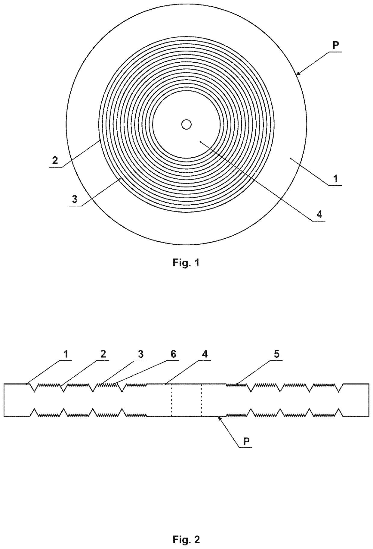
[0062]Referring firstly to FIG. 1, here there is shown a conventional basic gramophone plate P, with an outer annular ring 1 and an inner circular hub area 4, both of which regions 1, 4 are substantially flat and planar without any audio data recorded thereon. In between the unrecorded regions 1, 4 is a central annular region bearing recorded audio data, in the form of a continuous spiral groove comprising audio data log lines 2 whose cut shape and profile record the audio data, which is readable and capable of playback using convention stylus- or needle-based gramophone playback equipment. Located between individual audio data log lines 2 are planar lands or spaces 3, which—according to the present invention—can be exploited to new and advantageous effect by recording thereon visual image data.

[0063]FIG. 2 shows schematically an example of one such embodiment of the invention, in which interspersed between individual audio data log lines 2, on the lands or spaces 3 therebetween, ar...


PUM


Abstract

A gramophone plate (P) having at least one face, the at least one face including at least one region on which is recorded audio data (2), wherein the said at least one region of the at least one face also has at least one visual image (7), or a portion of at least one visual image, recorded thereon.

Description

TECHNICAL FIELD[0001]This invention relates to a gramophone plate, more particularly to a gramophone plate on at least one face of which is recorded one or more images, especially visual images, in addition to audio data recorded thereon.BACKGROUND AND PRIOR ART[0002]As used herein, the term “gramophone plate” means any generally flat, planar or disc-like plate or body on which is recorded, on at least a portion of at least one face thereof, audio data, such as in the form of a continuous spiral groove of varying shape (e.g. varying width and / or depth and / or cross-sectional profile) passing along its length. Such plates may typically be formed from vinyl or similar plastics material. Such a modulated spiral groove, whose width and / or depth is / are typically dimensioned at the order of a few micrometers (microns) up to a few tens of micrometers (microns) (e.g. a width of around 80 micrometers (microns) on a typical vinyl LP gramophone plate), thus records audio data in the form of the...

Claims


Application Information

Patent Timeline
IPC IPC(8): G06K19/06G11B3/78
CPCG06K19/06065G11B3/78G06K19/06121G06K19/06103G11B3/68G11B23/38B29D17/002G11B3/70G11B23/40
Inventor HOUHA, ROMANSKEREN, MAREKKVETON, MILANMATEJKA, MILAN
Owner IQ STRUCTURES SRO
Why Eureka
Try Eureka