Workflow engine for generating code based on visualizations

a workflow engine and visualization technology, applied in the field of computing, can solve problems such as the loss of the ability to combine loops or decouple the consumption of data, and achieve the effect of reducing the difficulty of generating source code, and improving the quality of work

Inactive Publication Date: 2021-07-22
ONTOLOGY PARTNERS
View PDF0 Cites 3 Cited by
  • Summary
  • Abstract
  • Description
  • Claims
  • Application Information

AI Technical Summary

Benefits of technology

This patent describes a new design tool that allows users to create workflows by drawing visual diagrams, with the tool automatically generating valid code. The tool also allows for the creation of loops and data binding, which are important but difficult to achieve with existing tools. The target language is orchestrated for a specific workflow engine, but the tool can also be used with other code types like JSON and XML.

Problems solved by technology

In some cases where the user does not leave the UI, the loops are trivial, and the expressiveness or ability to combine loops or decouple the consumption of the data is lost.

Method used


Image

  • Workflow engine for generating code based on visualizations
  • Workflow engine for generating code based on visualizations
  • Workflow engine for generating code based on visualizations

Examples


example ui

Schematics

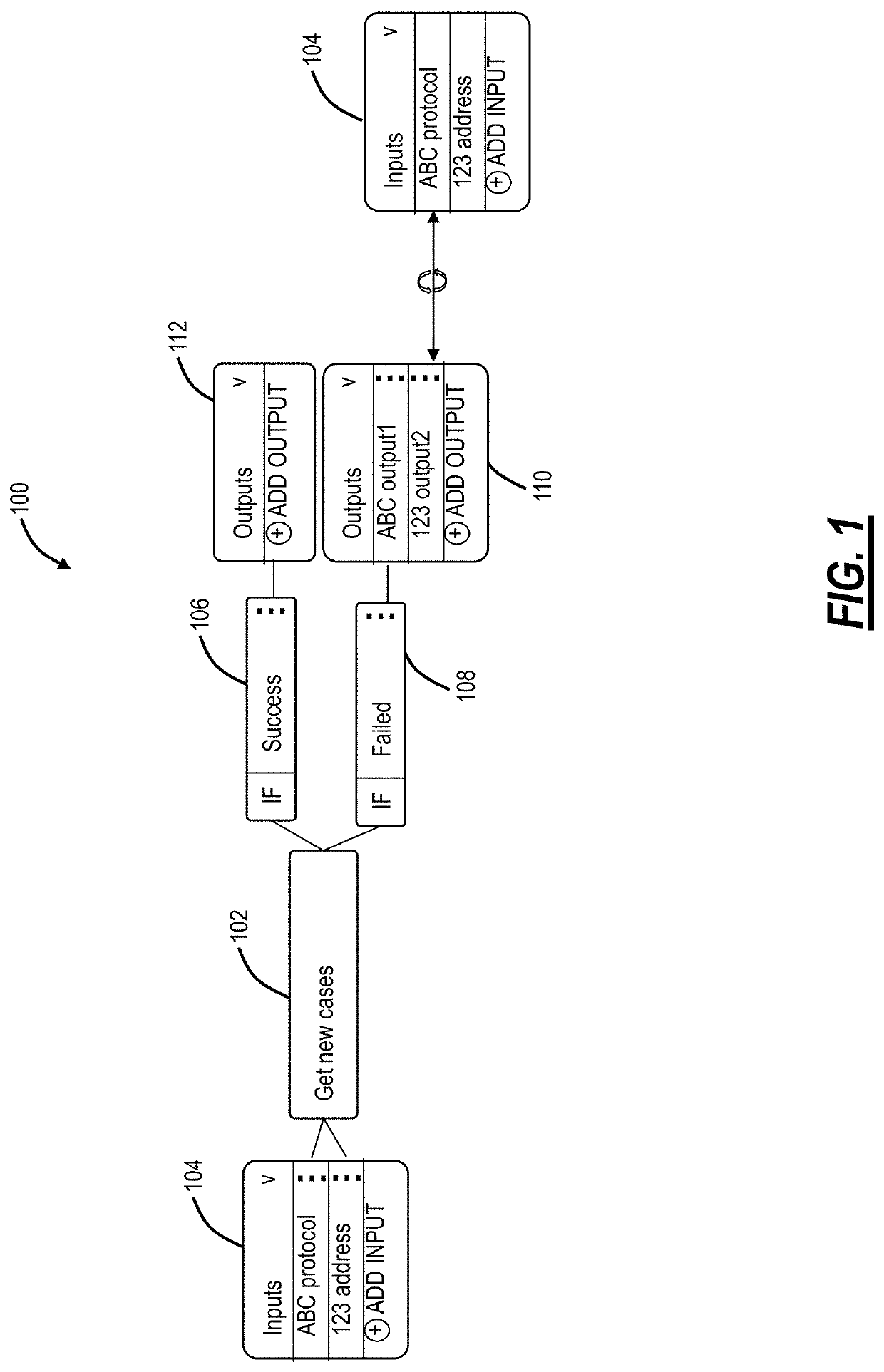
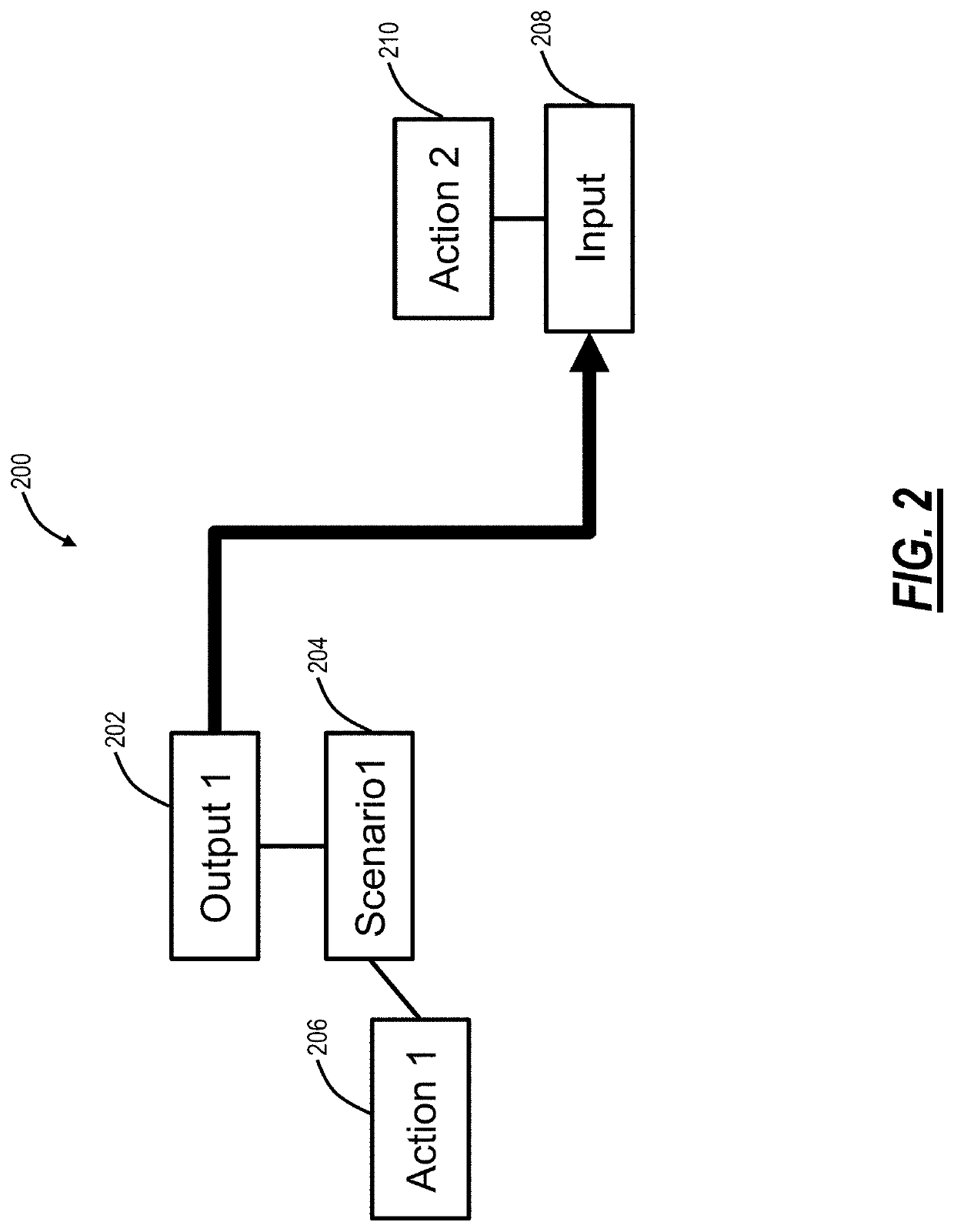
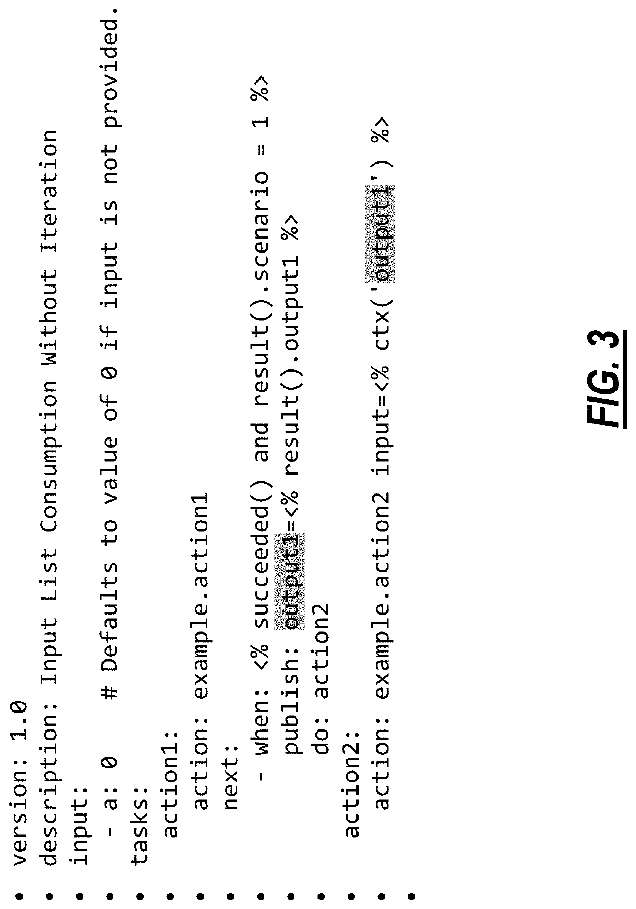
[0053]FIGS. 14-22 are diagrams of workflows illustrating a set of concepts and relations that are modeled in the abstract.

[0054]FIG. 14 is a diagram of a workflow 800A with actions, inputs, published, do-next, when, and types. Step 1 includes a box representing an ‘Action’ with the friendly name of the action displayed clearly. Double-clicking on this box brings up properties like an area to provide ‘comments’ on what this action is doing and why (the business case). Step 2 includes a list of all the inputs that this action accepts stacked on top of each other. It is possible to draw lines from an Input box to an Output box to describe the relationship here.

[0055]Step 3 includes a representation of the ‘when’ construct, each action has a set of predefined “when scenarios,” scenarios could be hidden or visible by default, this depends on user experience and the number of scenarios provided. Step 4 includes an alternative “when scenario” (colored in red to indicate error or ...

example processing

Device Architecture

[0077]FIG. 22 is a block diagram of a processing device 900 for implementing the design tool. The server 900 may be a digital computer that, in terms of hardware architecture, generally includes a processor 902, input / output (I / O) interfaces 904, a network interface 906, a data store 908, and memory 910. It should be appreciated by those of ordinary skill in the art that FIG. 22 depicts the processing device 900 in an oversimplified manner, and a practical embodiment may include additional components and suitably configured processing logic to support known or conventional operating features that are not described in detail herein. The components (902, 904, 906, 908, and 910) are communicatively coupled via a local interface 912. The local interface 912 may be, for example, but not limited to, one or more buses or other wired or wireless connections, as is known in the art. The local interface 912 may have additional elements, which are omitted for simplicity, suc...


PUM


Abstract

Systems and methods include presenting a user interface to a user for generating a workflow; obtaining a visualization of the workflow via the user interface, wherein the visualization is a directed graph with vertices including actions, scenarios for the actions, outputs, and inputs, and with directed edges between the vertices; and processing the visualization graph to generate code based thereon. The code can be YAML Ain't Markup Language (YAML), Extensible Markup Language (XML), and JavaScript Object Notation (JSON).

Description

CROSS-REFERENCE TO RELATED APPLICATION(S)[0001]The present disclosure relates to U.S. Provisional Patent Application No. 62 / 963,750, filed Jan. 21, 2020, and U.S. Provisional Patent Application No. 63 / 047,967, filed Jul. 3, 2020, the contents of which are incorporated by reference in their entirety.FIELD OF THE DISCLOSURE[0002]The present disclosure generally relates to computing. More particularly, the present disclosure relates to systems and methods for a workflow engine for generating code based on visualizations.BACKGROUND OF THE DISCLOSURE[0003]There are various software products, modules, applications, services, and / or devices available, each having inputs and providing outputs to perform some functionality. For illustration purposes, these are collectively referred to herein as applications or services, and it is noted these applications or services operate independently from one another. For example, the applications can be from different companies, can be developed by diff...

Claims


Application Information

Patent Timeline
Patent Type & Authority Applications(United States)
IPC IPC(8): G06F8/34
CPCG06F8/34
Inventor BURRELL, DANIEL
Owner ONTOLOGY PARTNERS
Why Eureka
Try Eureka