
Eureka
For R&D, Eureka makes reading and utilizing patents & technical documents easy.
Eureka AIR
Designed for self-driven R&D workflows. Generate viable solutions, solve complex R&D challenges, empower your innovation with AI.

Eureka Materials
Designed for material experts only. Revolutionize your material R&D, from search, analyze, to developing new materials.

TechResearch
Generate reliable direction feasibility study reports for your R&D in just a few steps.

TechSeek
Discover and master advanced knowledge NOW. Basics, ideas, possibilities, all at once.

TechMind
As an expert in R&D Theories, TechMind can generates customized viable solutions instantly.

TechRisk
Analyze your overall solution with one click, know your potential R&D risks in advance.

TechMonitor
Get weekly tech updates, stay abreast of the latest tech innovations and key insights.
Air purification device
- Summary
- Abstract
- Description
- Claims
- Application Information
AI Technical Summary
Benefits of technology
Problems solved by technology
Method used
Image

Examples
first embodiment
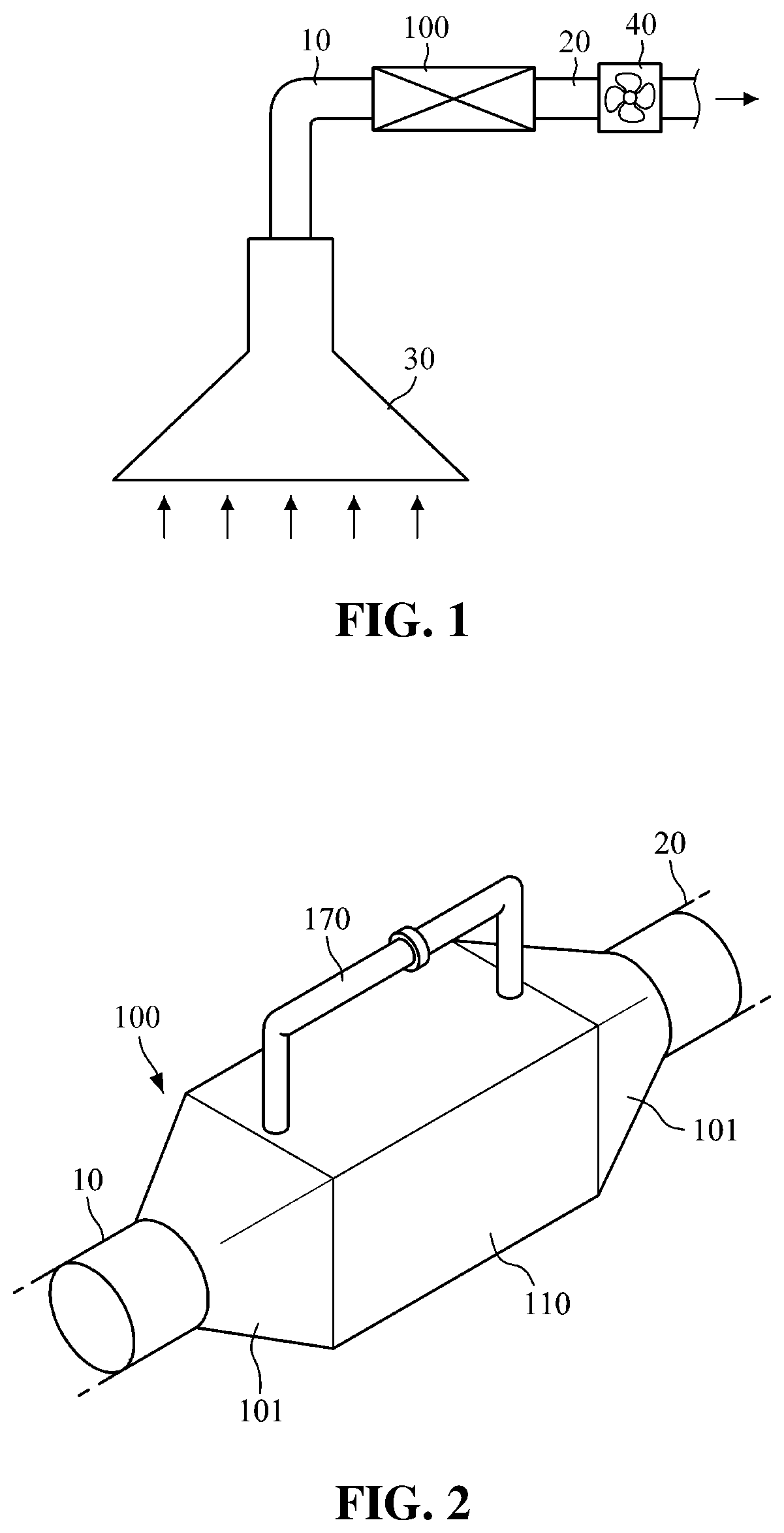
[0032]FIG. 1 is a configuration view illustrating an example in which an inlet duct and an outlet duct are employed in an air purification device according to the present invention.
[0033]As shown in FIG. 1, an air purification device 100 according to the first embodiment of the present invention is installed between an inlet duct 10 and an outlet duct 20. The air purification device 100 may suck and discharge contaminated air in a room through a hood 30 mounted above a countertop of a home or restaurant. At this time, a suction force is provided by an exhaust fan 40 installed in the outlet duct 20, and a movement passage is secured through the inlet duct 10 and the outlet duct 20, such that the sucked indoor air may be discharged to an outside.
[0034]The air purification device 100 according to the first exemplary embodiment of the present invention may remove foreign matters from the contaminated air introduced from a room through the inlet duct 10 to purify the air, and then discha...
second embodiment
[0078]FIG. 10 is a perspective view illustrating an air purification device according to the present invention, and FIG. 11 is a cross-sectional view of the air purification device shown in FIG. 10 taken on a line in the length direction of the housing.
[0079]Referring to FIGS. 10 and 11, an air purification device 200 according to the second embodiment of the present invention includes a housing 210, a filter 220, a heater 230, an inlet pipe damper 241, an outlet pipe damper 242, and a backwash intake port 251, an intake port damper 252, a backwash pipe 253, a backwash pipe damper 254, and a controller 270.
[0080]Air introduced into a passage section 212 from a room through an inlet pipe 211 of the housing 210 by the exhaust fan 40 (see FIG. 1) is discharged to an outside through an outlet pipe 213. The inlet pipe 211 is communicated with the inlet duct 10 (see FIG. 1) so that the contaminated air may be introduced. The outlet pipe 213 may be communicated with the outlet duct 20 (see...
PUM
 Abstract
Description
Claims
Application Information
 - R&D Engineer
- R&D Manager
- IP Professional
- Industry Leading Data Capabilities
- Powerful AI technology
- Patent DNA Extraction
Browse by: Latest US Patents, China's latest patents, Technical Efficacy Thesaurus, Application Domain, Technology Topic, Popular Technical Reports.
© 2024 PatSnap. All rights reserved.Legal|Privacy policy|Modern Slavery Act Transparency Statement|Sitemap|About US| Contact US: help@patsnap.com