Resonant machine learning algorithms, architecture and applications
- Summary
- Abstract
- Description
- Claims
- Application Information
AI Technical Summary
Benefits of technology
Problems solved by technology
Method used
Image

Examples
example 1
in an LC Tank
[0320]Consider the parallel LC tank circuit shown in FIG. 11, with VC and VL being the voltages across the capacitor C and inductor L respectively. IC and IL denote the corresponding currents flowing through the elements. Thus, VS=VL=VC and IS=IL+IC. Considering the LC tank to be driven by the voltage source VS at a frequency ω, the following condition exists in steady-state:
Is(ω)=Vs(ω)jωL[1-ω2LC]Eqn.(63)
[0321]Resonant condition of the circuit is achieved when
ω=1LC⇒Is(ω)=0-Eqn.(64)
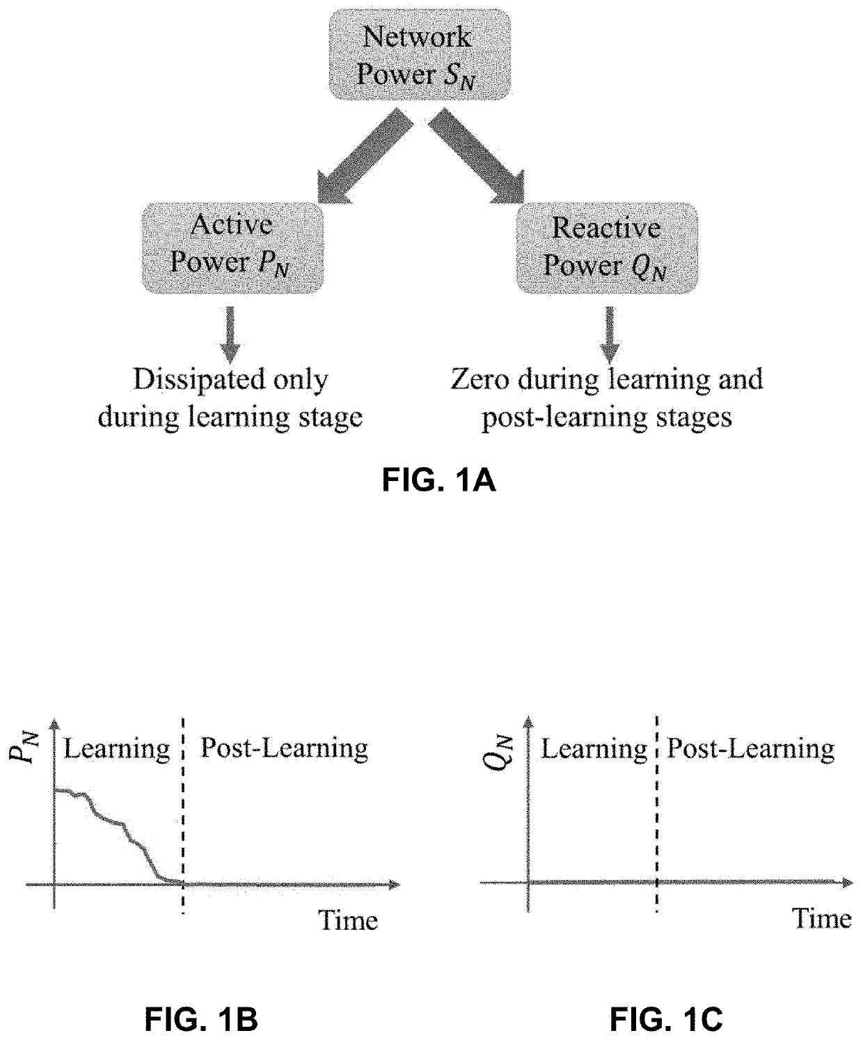
[0322]This result implies that the apparent power, SN=PN+jQN=VSIS*+VLIL*+VCIC* where the active power PN=0. Additionally at resonance, the reactive power
QN=QC+QL=VLIL*+VCIC*=-jωLV(ω)2+jωLV(ω)2=0.
Here QC and QL are the reactive powers associated with the capacitance and inductance respectively.
example 2
Generic Optimization Problem to the Equivalent Network Model
[0323]Consider an optimization problem defined over a probabilistic domain, given by the following generic form:
min{xi}ℋ({xi})s.t.∑i=1Nxi=1,xi≥0Eqn.(65)
[0324]Eqn. (65) may be mapped to the electrical network-based model described above by replacing xi=|Vi|2+|Ii|2, which leads to the following problem in the {|Vi|2, |Ii|2} domain:
min{Vi,Ii}ℋ({Vi,Ii})s.t.∑i=1N(Vi2+Ii2)=1Eqn.(66)
[0325]Note that the method also works for optimization problems defined over non-probabilistic domains, of the following form:
min{xi}ℋ({xi})s.t.xi≤1,xi∈ℝ∀i=1,…,N.Eqn.(67)
[0326]This can be done by considering xi=xi+−xi−∀i, where both xi+, xi−≥0. Since by triangle inequality, |xi|=|xi+|+|xi−|, enforcing xi++xi−=1 ∀i would automatically ensure |xi|≤1 ∀i, resulting in the following expression:
argmin{xi}ℋ({xi})≡argmin{xi+,xi-}ℋ({xi+,xi-})s.t.xi≤1,xi∈ℝs.t.xi++xi-=1,xi+,xi-≥0Eqn.(68)
[0327]The replacements xi+=|Vi|2, xi−=|Ii|2...
example 3
rowth Transform Dynamical Systems
[0329]Consider the optimization problem in Equation (65) again. We can use the Baum-Eagon inequality to converge to the optimal point of H in steady state, by using updates of the form:
xi←xi(∂ℋ({xi})∂ℋxi+λ)Σk=1Nxk(-∂ℋ({xk})∂ℋxk+λ),Eqn.(70)
[0330]Here, H is assumed Lipschitz continuous on the domain D={xi, . . . , xn:Σi=1Nxi=1, xi≥0 ∀i}⊂+N. The constant λ∈R+ is chosen such that
-∂ℋ({xi})∂ℋxi+λ>0,∀i.
[0331]The optimization problem given by Equation (10) may be solved by using the growth transforms discussed above. The outline of the proof is as follows: (1) starting with a generic magnitude domain optimization problem without any phase regularizer, derive the form for the growth trans-form dynamical system which would converge to the optimal point asymptotically; (2) derive a complex domain counterpart of the above, again without phase constraints; (3) derive the complex domain dynamical system by incorporating a phase regularizer in the obj...
PUM
 Abstract
Description
Claims
Application Information
 - R&D
- Intellectual Property
- Life Sciences
- Materials
- Tech Scout
- Unparalleled Data Quality
- Higher Quality Content
- 60% Fewer Hallucinations
Browse by: Latest US Patents, China's latest patents, Technical Efficacy Thesaurus, Application Domain, Technology Topic, Popular Technical Reports.
© 2025 PatSnap. All rights reserved.Legal|Privacy policy|Modern Slavery Act Transparency Statement|Sitemap|About US| Contact US: help@patsnap.com