

Automotive frame member and electric vehicle
- Summary
- Abstract
- Description
- Claims
- Application Information
AI Technical Summary
Benefits of technology
Problems solved by technology
Method used
Image

Examples
first embodiment
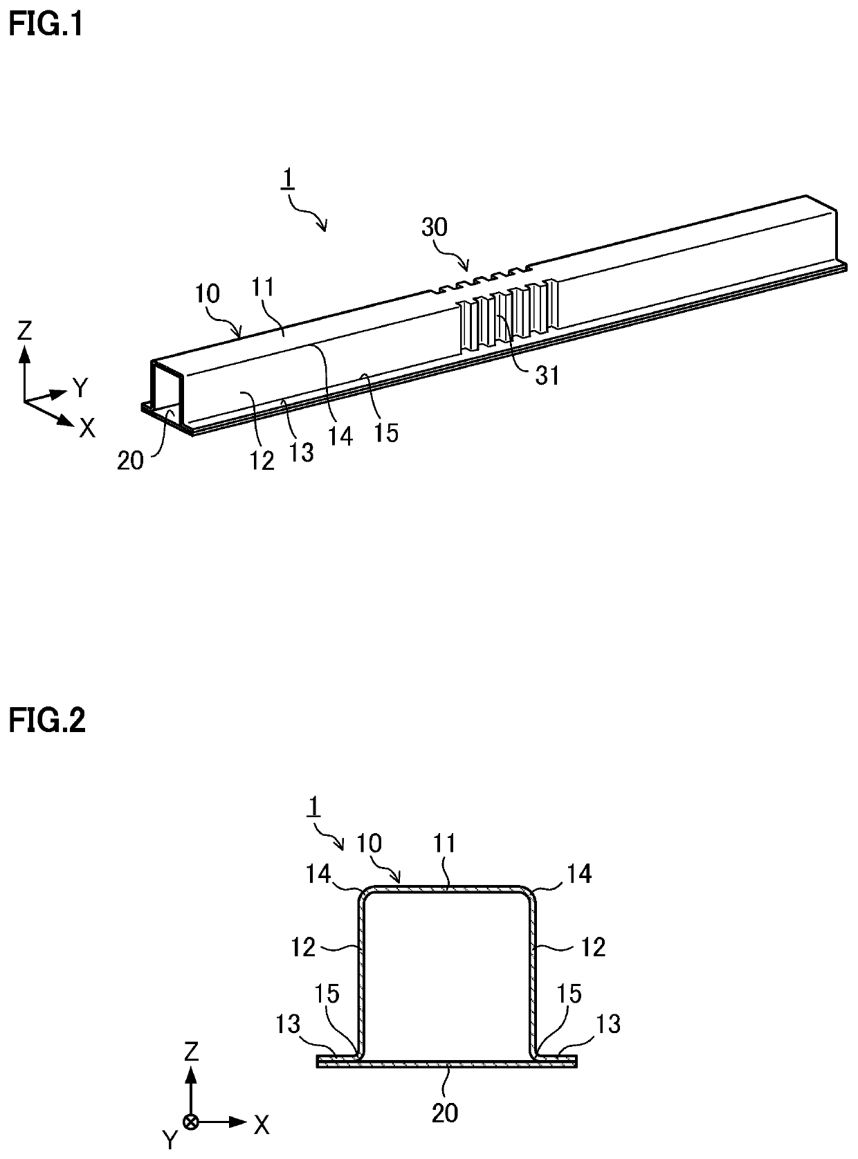
[0043]FIG. 1 is a view illustrating a schematic configuration of an automotive frame member 1 in a first embodiment. The automotive frame member 1 is a member that receives a bending load, such as a side sill or a bumper beam. The automotive frame member 1 of the first embodiment has a hat member 10 being a member whose cross section vertical to a member longitudinal direction (Y direction in FIG. 1) has a hat shape, and a flat closing plate 20 being a bottom plate that is joined to the hat member 10. Note that an X direction, the Y direction, and a Z direction illustrated in FIG. 1 are directions which are vertical to one another, and when the automotive frame member 1 is a member configuring a side sill, for example, the X direction is a vehicle height direction, the Y direction is a vehicle length direction, and the Z direction is a vehicle width direction. Further, when the automotive frame member 1 is a member configuring a bumper beam, for example, the X direction is the vehic...
second embodiment
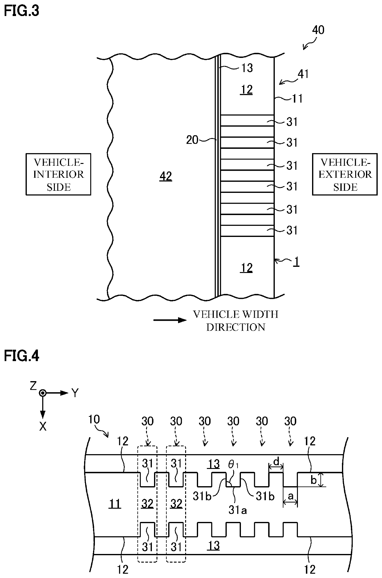
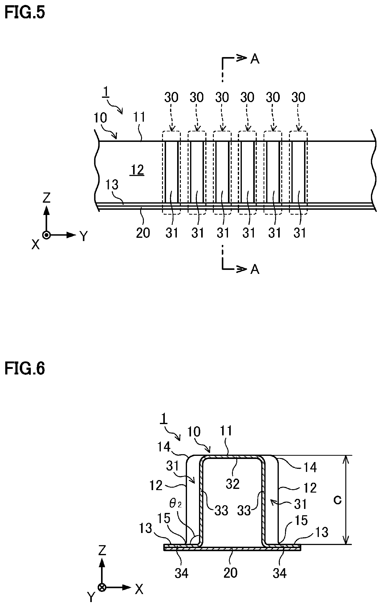
[0058]As illustrated in FIG. 12 and FIG. 13, in an automotive frame member 1 of a second embodiment, the groove part 31 does not extend to the ridge line portion 14 of the hat member 10. Specifically, in the automotive frame member 1 of the second embodiment, one end of the groove part 31 extends to a vehicle-interior-side end portion of the vertical wall 12 (the ridge line portion 15 in an example of FIG. 14), but the other end of the groove part 31 does not extend to a vehicle-exterior-side end portion of the vertical wall 12 (the ridge line portion 14 in the example of FIG. 14). Even with the groove part 31 having such a shape, when the width a of the groove part 31, the depth b of the groove part 31, and the height c of the vertical wall 12 of the hat member 10 satisfy the relations of 0.2≤a / c≤0.3 and 0.2≤b / c≤0.3, it becomes easy to cause the deformation in the axial crush mode, resulting in that the energy absorption efficiency can be improved.
[0059]FIG. 14 is a view illustrati...
third embodiment
[0062]In the automotive frame member 1 in the first embodiment, a mating member of the hat member 10 is the closing plate 20. In an automotive frame member 1 in the second embodiment illustrated in FIG. 15, a mating member is also a hat member. In the explanation below, the hat member described in the first embodiment (the upper member in FIG. 15) is referred to as a “first hat member 10a”, and a hat member to be a mating member of the first hat member 10a (the lower member in FIG. 15) is referred to as a “second hat member 10b”. The second hat member 10b also has the top plate 11, the pair of vertical walls 12 connected to the top plate 11, and the flanges 13 connected to the vertical walls 12, similarly to the first hat member 10a. The first hat member 10a and the second hat member 10b are joined by their flanges 13, to thereby configure the automotive frame member 1. Also in the automotive frame member 1 in the second embodiment, the groove part 31 of the first hat member 10a has...
PUM
 Abstract
Description
Claims
Application Information