Rotatable door structure and electronic device casing therewith

a door structure and electronic device technology, applied in the direction of electric apparatus casings/cabinets/drawers, instruments, wing arrangements, etc., can solve the problem of easy loss of screws, and achieve the effect of avoiding structural interferen

Active Publication Date: 2021-08-12
WISTRON CORP
View PDF0 Cites 1 Cited by
  • Summary
  • Abstract
  • Description
  • Claims
  • Application Information

AI Technical Summary

Benefits of technology

[0006]An electronic device casing according to the invention includes a rotatable door structure. The rotatable door structure includes a fixed casing, a door cover, and a hinge. The fixed casing has an accommodating recess, which forms an opening and has at least one peripheral interface window. The door cover is pivotally connected to the fixed casing through the hinge. The hinge includes a shaft and a connection part. The shaft has a first cam surface. The connection part is rotatably connected to the shaft relative to a rotation axis. The connection part has a second cam surface opposite to the first cam surface. Therein, when the door cover rotates through the hinge relative to fixed casing to expose the opening, the first cam surface and the second cam surface abut against each other to make the door cover move away relative to the fixed casing along the rotation axis. Thereby, the opening can be exposed without removing the door cover from the fixed casing. A user can manipulate objects in the accommodating recess through the opening, e.g. inserting or extracting connection cables. Furthermore, when rotating, the door cover moving along the rotation axis is conducive to avoidance of structural interference with the fixed casing or the objects in the accommodating recess.

Problems solved by technology

Besides, it is easy to lose the detached screws.

Method used


Image

  • Rotatable door structure and electronic device casing therewith
  • Rotatable door structure and electronic device casing therewith
  • Rotatable door structure and electronic device casing therewith

Examples


Embodiment Construction

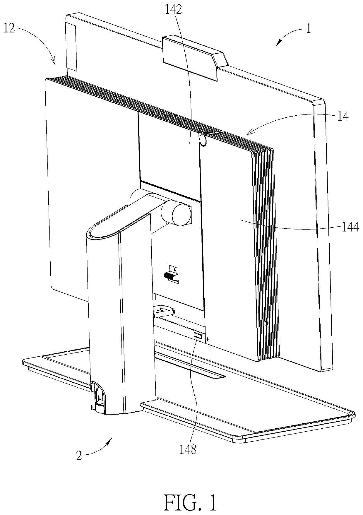
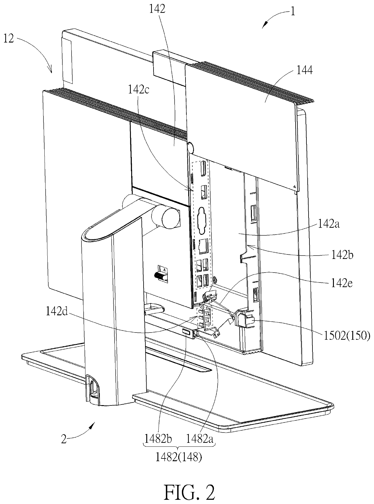
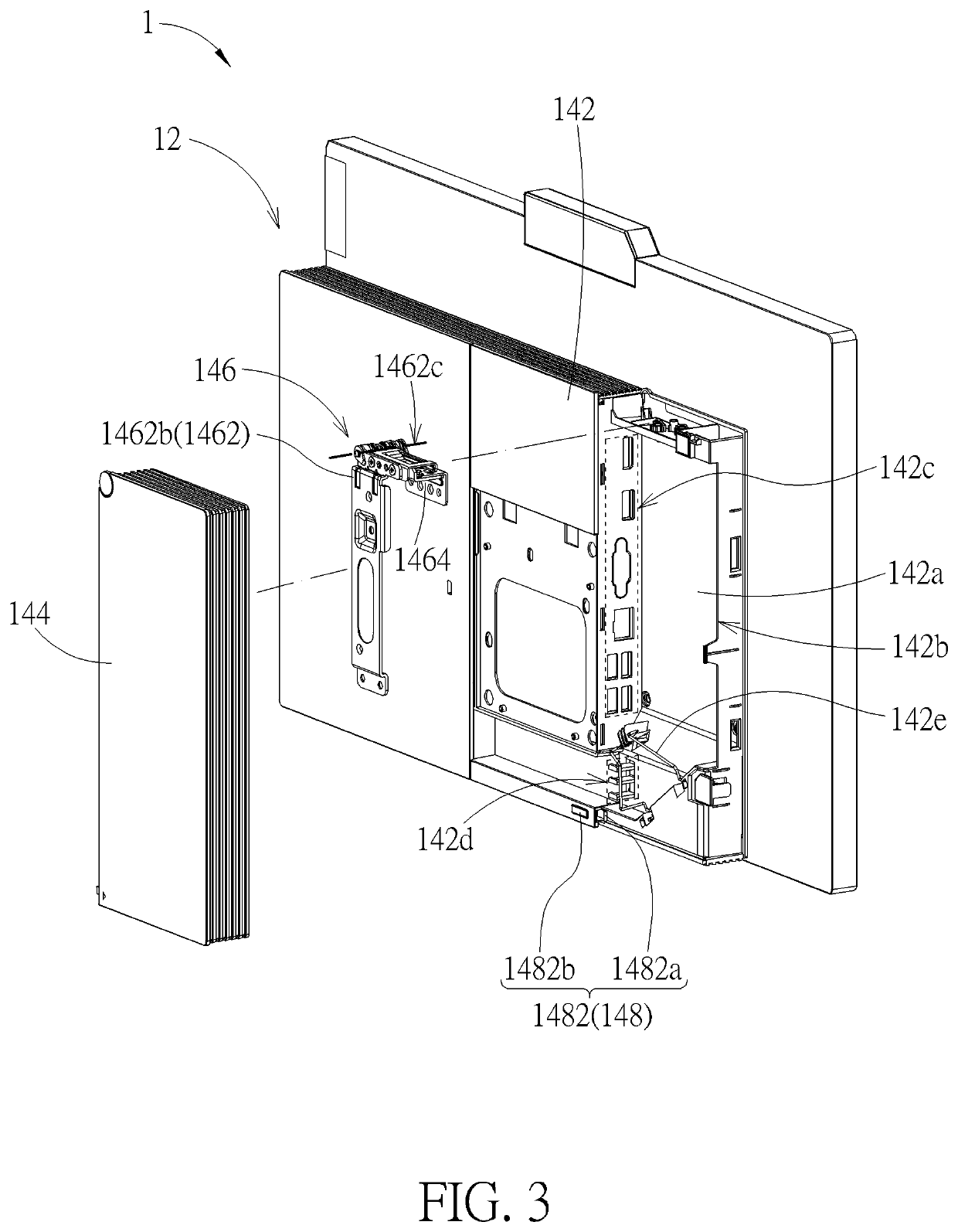
[0021]Please refer to FIG. 1 to FIG. 3. An electronic device casing 1 according to an embodiment can be used in, but not limited to, all-in-one PCs, smart TVs, monitors, and so on. The electronic device casing 1 is supported by a mount 2 for convenience of disposing the electronic device casing 1 on a desk. The electronic device casing 1 includes a back casing assembly 12, on which a rotatable door structure 14 is disposed. The rotatable door structure 14 includes a fixed casing 142, a door cover 144, and a hinge 146. The fixed casing 142 has an accommodating recess 142a forming an opening 142b. The door cover 144 is pivotally connected to the fixed casing 142 through the hinge 146, so that the door cover 144 can rotate relative to the fixed casing 142 to an open position for exposing the opening 142b (as shown by FIG. 2, in which the rotatable door structure 14 is at an open status), or to a closed position for covering the opening 142b (as shown by FIG. 1, in which the rotatable d...


PUM


Abstract

A rotatable door structure includes a fixed casing, a door cover, and a hinge. The fixed casing has an opening. The door cover is pivotally connected to the fixed casing through the hinge. The hinge includes a shaft and a connection part. The shaft has a cam surface. The connection part has another cam surface and is rotatably connected to the shaft relative to a rotation axis. When the door cover rotates relative to the fixed casing through the hinge so as to expose the opening, the two cam surfaces abut against each other to move the door cover away relative to the fixed casing along the rotation axis. An electronic device casing includes the above rotatable door structure. Therein, the fixed casing includes an accommodating recess, which forms the opening and has at least one peripheral interface window.

Description

BACKGROUND OF THE INVENTION1. Field of the Invention[0001]The present invention relates to an electronic device casing, and more particularly to an electronic device casing with an openable door cover.2. Description of the Prior Art[0002]Some electronic devices have several peripheral connection ports. For avoidance of messy connection cables or hooking connection cables, these connection cables are usually fixed by a cable tie or other cable-arrangement structures. Some electronic devices further use a door cover to cover the connection cables for the protection of the connection cables and for the beautification of the electronic devices. In the latter, the door cover is usually fixed onto the casing of the electronic device by screwing with screws or hooking the casing with hooks. When a cable is required to be inserted in or extracted out, a user needs to detach the door cover from the casing. The method of screwing with screws needs corresponding tools for operation. Besides, i...

Claims


Application Information

Patent Timeline
Patent Type & Authority Applications(United States)
IPC IPC(8): G06F1/16G06F1/18
CPCG06F1/1601G06F2200/1612G06F1/1637G06F1/181H05K5/0217E06B5/00E06B3/34G06F1/16G06F2200/1631G06F1/183
Inventor LIU, YUANQINGHE, HUIQIANGCHEN, DONG-YINGKUO, CHUN-HONG
Owner WISTRON CORP
Why Eureka
Try Eureka