Large-power charging and cooling device with high energy efficiency ratio and high cooling efficiency

A high-power charging and cooling efficiency technology, applied in charging stations, electric vehicle charging technology, refrigerators, etc., can solve the problems of long start-up time, low cooling efficiency, low energy efficiency ratio, etc., and achieve improved refrigeration energy efficiency ratio and cooling capacity Small loss, good heat exchange effect

Active Publication Date: 2019-05-03
JIANGSU WANBANG DEHE NEW ENERGY TECH CO LTD
View PDF4 Cites 1 Cited by
  • Summary
  • Abstract
  • Description
  • Claims
  • Application Information

AI Technical Summary

Problems solved by technology

[0006] To sum up, the high-power charging and cooling system 17 of the prior art adopts a single technical scheme of compression refrigeration and heat exchange of the evaporator 18 in the water tank 19, which has low energy efficiency ratio and high energy consumption
[0007] In addition, the way the evaporator 18 cools the water tank 19 requires a long start-up time to lower the temperature of the water tank 19 to the target temperature, which cannot be cooled quickly, and is not suitable for high-power fast charging systems exceeding 350kW
Specifically, due to the fast charging speed, the high-power fast charging system can fully charge the vehicle battery within 10 minutes, and if the start-up time of the matching cooling device takes 1-2 minutes, the design is unreasonable, that is, the start-up time is long, Slow cooling speed and low cooling efficiency

Method used


Image

  • Large-power charging and cooling device with high energy efficiency ratio and high cooling efficiency
  • Large-power charging and cooling device with high energy efficiency ratio and high cooling efficiency
  • Large-power charging and cooling device with high energy efficiency ratio and high cooling efficiency

Examples


Embodiment Construction

[0040] The present invention is described in further detail now in conjunction with accompanying drawing. These drawings are all simplified schematic diagrams, which only illustrate the basic structure of the present invention in a schematic manner, so they only show the configurations related to the present invention.

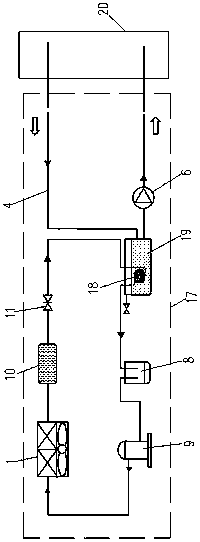
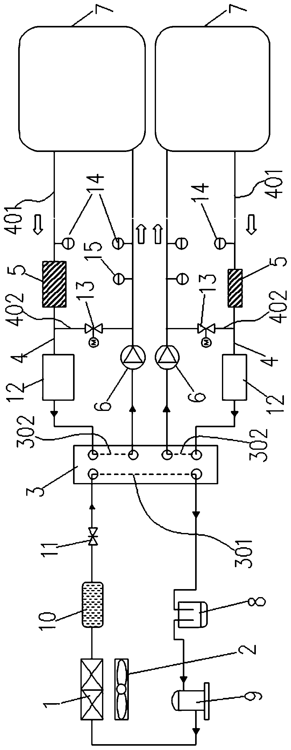
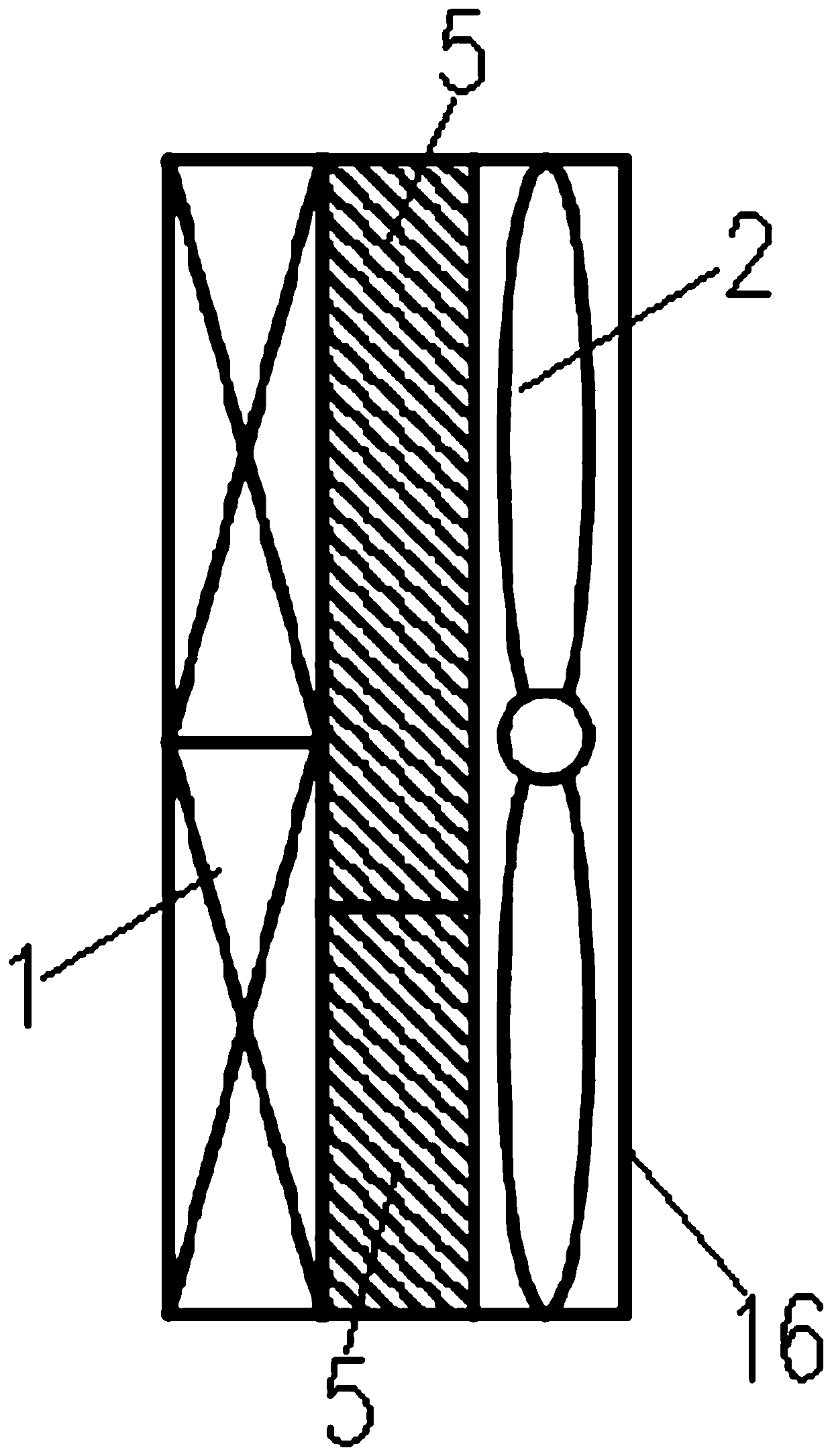
[0041] like Figure 2-Figure 3 Shown is a specific embodiment of a high-power charging cooling device with high energy efficiency ratio and high cooling efficiency of the present invention, which includes a vapor compression refrigeration system and two cooling circuits 4, and a condenser 1 of the vapor compression refrigeration system. There is a fan 2 on the side, and the evaporator of the vapor compression refrigeration system is a three-medium plate heat exchanger 3, and the three-medium plate heat exchanger 3 is equipped with a cold path 301 and two hot paths 302, and the cold path 301 is set on the steam In the refrigeration circuit of the compression r...


PUM


Abstract

The invention belongs to the technical field of cooling, and specifically relates to a large-power charging and cooling device with high energy efficiency ratio and high cooling efficiency. The large-power charging and cooling device with high energy efficiency ratio and high cooling efficiency includes a steam compression-type refrigerating system and two cooling circuits, wherein a fan is arranged at one side of a condenser of the steam compression-type refrigerating system; an evaporator of the steam compression-type refrigerating system is a three-medium plate type heat exchanger; one cooling stroke and two heating strokes are arranged in the three-medium plate type heat exchanger; the cooling stroke is arranged in the cooling circuits of the steam compression-type refrigerating system; each heating stroke is correspondingly arranged in each cooling circuit one to one; each cooling circuit is provided with a finned tube radiator and a pump body; and each finned tube radiator is clamped between the fan and the condenser. The large-power charging and cooling device with high energy efficiency ratio and high cooling efficiency has the advantages that: cooling and cooling, each finned tube radiator and the condenser are cooled step by step by the air cooling technology while performing compression cooling, thus improving the cooling energy efficiency ratio, reducing the energyconsumption, improving the cooling rate of each liquid cooling terminal, being high in the cooling efficiency, and having no start-up preparation time.

Description

technical field [0001] The invention belongs to the technical field of cooling, and in particular relates to a high-power charging cooling device with high energy efficiency ratio and high cooling efficiency. Background technique [0002] High-power charging, that is, HPC, has the advantages of short vehicle charging time and short queuing time, so the market space for high-power charging will become larger and larger. [0003] In terms of temperature, when high-power charging is used, the transmission capacity per unit time will increase, and the temperature rise of cables and terminals will increase a lot, so a cooling system needs to be added to ensure charging safety. [0004] For example, if figure 1 In the high-power charging cooling system 17 shown in the prior art, the left circuit is a refrigeration circuit: the gaseous refrigerant passes through the compressor 9, is compressed into a high-temperature liquid, and then cooled to a normal temperature liquid through t...

Claims


Application Information

Patent Timeline
Patent Type & Authority Applications(China)
IPC IPC(8): B60L53/302F25B1/00F25B41/00F25B41/42
CPCY02T90/16
Inventor 谢哲男邵丹薇李德胜储丹杨志
Owner JIANGSU WANBANG DEHE NEW ENERGY TECH CO LTD
Why Eureka
Try Eureka