Charging connector

Active Publication Date: 2021-08-19
JAPAN AVIATION ELECTRONICS IND LTD
View PDF0 Cites 0 Cited by
  • Summary
  • Abstract
  • Description
  • Claims
  • Application Information

AI Technical Summary

Benefits of technology

The present invention relates to a charging connector with a lever that is designed to prevent damage to the latch portion when the connector is forcibly pulled away from the inlet. The lever has a reinforcing portion made of metal plate and the locking portion of the reinforcing portion is exposed on the locking surface of the locking lug of the latch portion. When the lever is positioned at the locked position, the regulating portion of the charging connector regulates forward movement of the reinforcing portion in the front-rear direction. This results in a stronger latch portion that can withstand the force of being permanently detached from the inlet.

Problems solved by technology

If a charging connector such as that of Patent Document 1 continues to be forcibly pulled in the negative X-direction under a state where a latch portion is engaged with an inlet, the latch portion might be damaged so that the charging connector might be removed from the inlet.

Method used


Image

  • Charging connector
  • Charging connector
  • Charging connector

Examples


Embodiment Construction

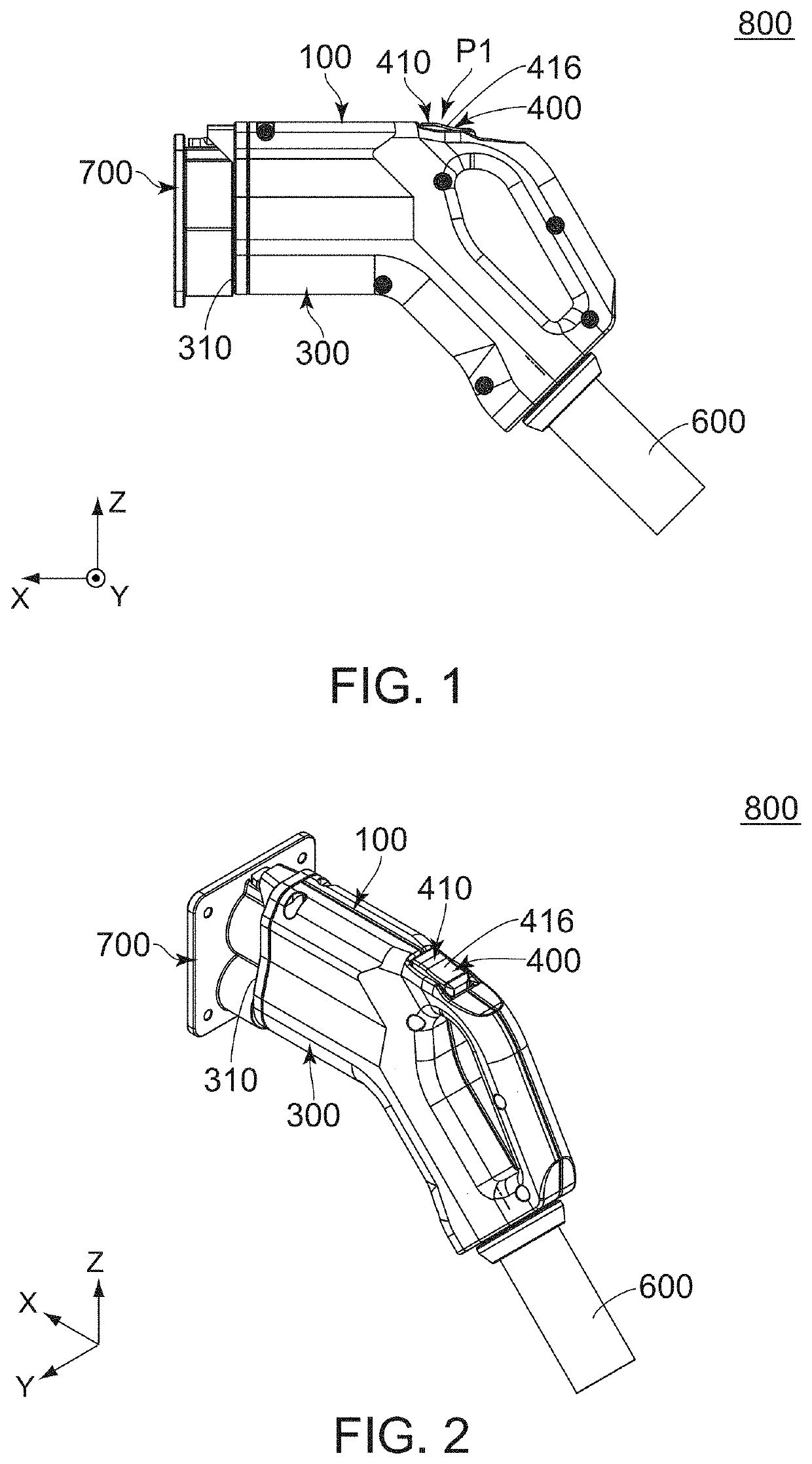
[0039]As shown in FIGS. 1 and 2, a charging connector assembly 800 according to an embodiment of the present invention comprises an inlet 700 and a charging connector 100.

[0040]As shown in FIGS. 1 and 8, the inlet 700 of the present embodiment is positioned forward of the charging connector 100 in a front-rear direction. In the present embodiment, the front-rear direction is an X-direction. Specifically, forward is a positive X-direction while rearward is a negative X-direction. As shown in FIGS. 9 and 27, the inlet 700 has a locked portion 710 and a mating portion receiving portion 720.

[0041]As shown in FIG. 9, the locked portion 710 of the present embodiment has a locked surface 712. The locked surface 712 faces forward in the front-rear direction.

[0042]As shown in FIG. 9, the mating portion receiving portion 720 of the present embodiment is a space which is recessed forward in the front-rear direction.

[0043]As shown in FIGS. 1 and 2, the charging connector 100 of the present embo...


PUM


Abstract

A charging connector comprises a connector main, a lever and a regulating portion. The lever has a latch portion. The latch portion is provided with a locking lug. The locking lug has a locking surface. The lever comprises a main portion and a reinforcing portion. The main portion is made of resin. The reinforcing portion is made of metal plate. The reinforcing portion is held by the main portion. The reinforcing portion has a locking portion and a regulated portion. The locking portion is exposed on the locking surface. When the lever is positioned at a locked position, the regulated portion is positioned rearward beyond the regulating portion in a front-rear direction and faces the regulating portion in the front-rear direction. When the lever is positioned at the locked position, the regulating portion regulates forward movement of the regulated portion in the front-rear direction.

Description

BACKGROUND OF THE INVENTION[0001]This invention relates to a charging connector which is mateable with an inlet.[0002]As shown in FIG. 28, Patent Document 1 discloses a charging connector 900 which is mateable with an inlet (not shown) along an X-direction. The charging connector 900 comprises a connector main 910 and a lever 930. The lever 930 is held by the connector main 910 so as to be movable between a locked position and a released position in a seesaw manner. The lever 930 has a latch portion 940. The latch portion 940 is engaged with the inlet when the charging connector 900 is mated with the inlet. As shown in FIG. 29, the latch portion 940 is provided with a locking lug 942 and reinforcing libs 944. The locking lug 942 has a locking surface 9422. The locking surface 9422 faces in a negative X-direction when the lever 930 is positioned at the locked position. If the charging connector 900 is forcibly pulled in the negative X-direction under a state where the latch portion 9...

Claims


Application Information

Patent Timeline
IPC IPC(8): H01R13/639H01R13/627H01R13/641B60L53/16H01R13/508
CPCH01R13/639H01R13/6275H01R13/508B60L53/16H01R13/641H01R13/635H01R2201/26H01R13/6397Y02T10/70Y02T10/7072Y02T90/14
Inventor TAKAGI, YOUHEI
Owner JAPAN AVIATION ELECTRONICS IND LTD
Why Eureka
Try Eureka