Working vehicle

a technology for working vehicles and hoses, which is applied in the direction of endless track vehicles, soil shifting machines/dredgers, transportation and packaging, etc., can solve the problems of increasing costs and damage to hydraulic hoses, and achieve the effect of restricting the free movement of hydraulic hoses

Pending Publication Date: 2021-08-26
YANMAR POWER TECHNOLOGY CO LTD
View PDF0 Cites 2 Cited by
  • Summary
  • Abstract
  • Description
  • Claims
  • Application Information

AI Technical Summary

Benefits of technology

[0015]According to the present invention, the hydraulic hoses can be designed to have a minimum required length.
[0016]According to the present invention, it is possible to restrict the free movement of the hydraulic hoses without forcibly bending the hydraulic hoses.

Problems solved by technology

This leads to a concern in that the hydraulic hoses may be damaged due to contact with falling objects or obstacles.
This leads to an increase in cost.

Method used


Image

  • Working vehicle
  • Working vehicle
  • Working vehicle

Examples


Embodiment Construction

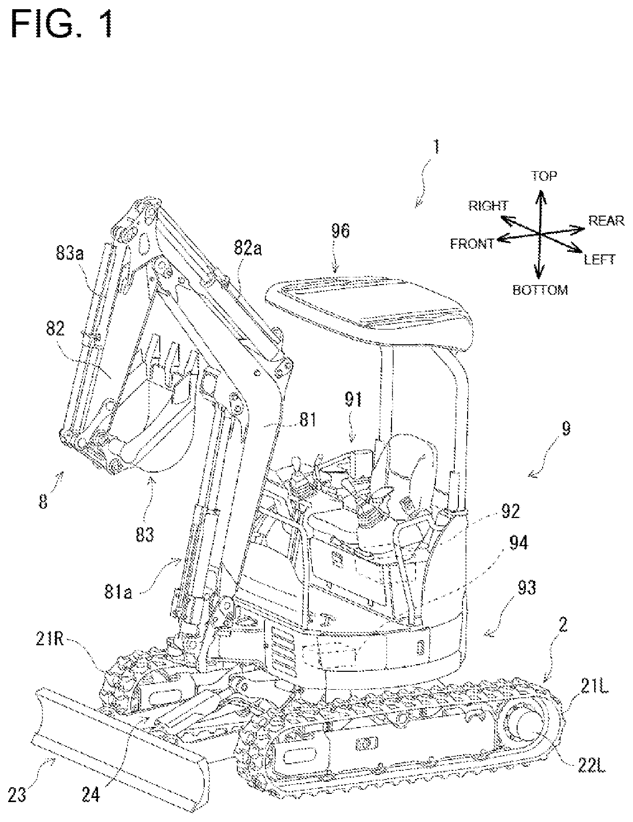
[0023]Embodiments of the present invention will now be described with reference to the drawings. A backhoe will be described as an example of a working vehicle of the present embodiment. However, the working vehicle is not limited to a backhoe, and may be any other vehicle, such as a wheel loader. Note that, in the drawings, the vehicle traveling direction is denoted by “front” and “rear,” the vehicle width direction is denoted by “left” and “right,” and the vehicle height direction is denoted by “top” and “bottom.” When indicating placement, “front” refers to the front in the forward direction, and “rear” refers to the rear in the forward direction. “Right” refers to the right in the width direction of the vehicle when facing the “front,” and “left” refers to the left in the width direction of the vehicle when facing the “front.”

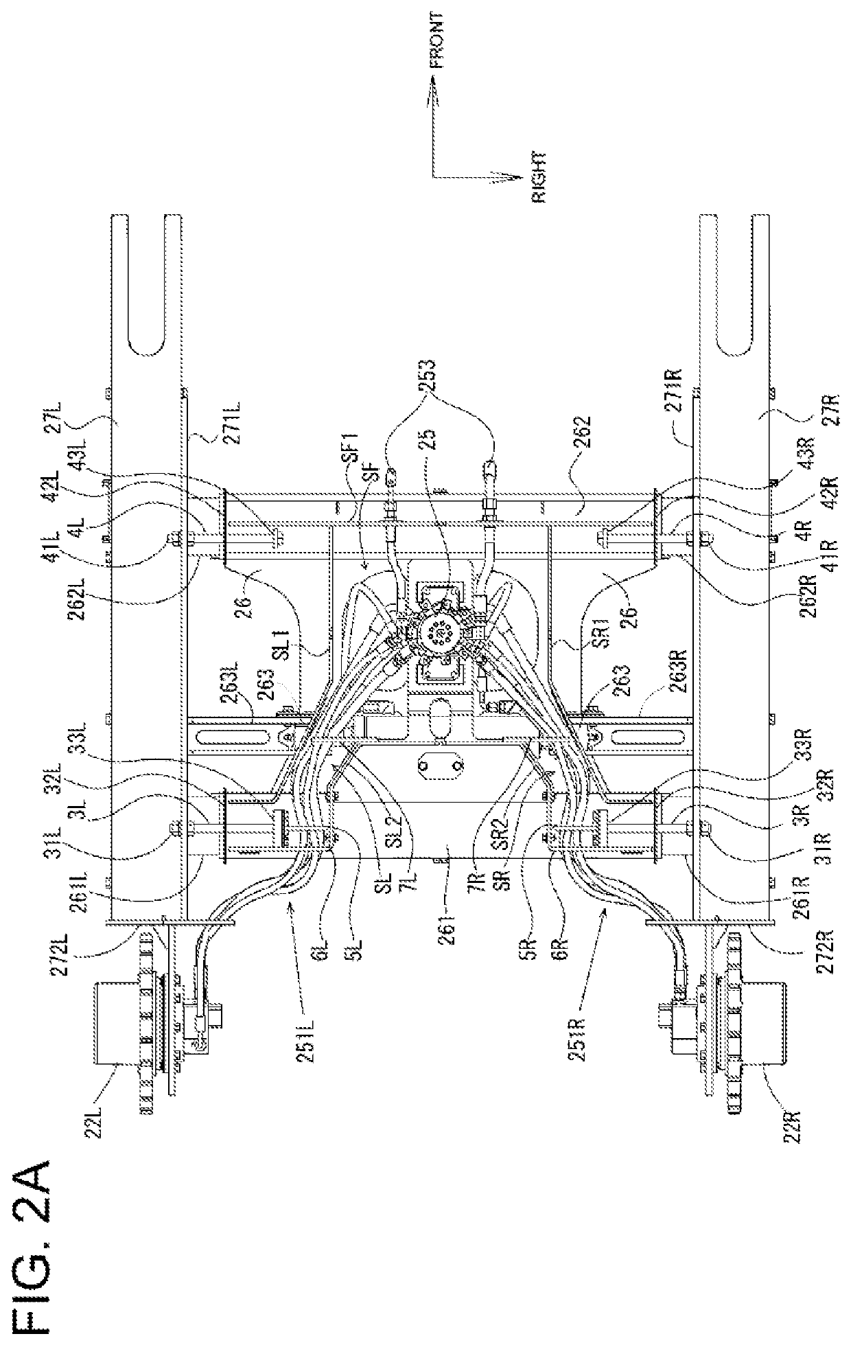
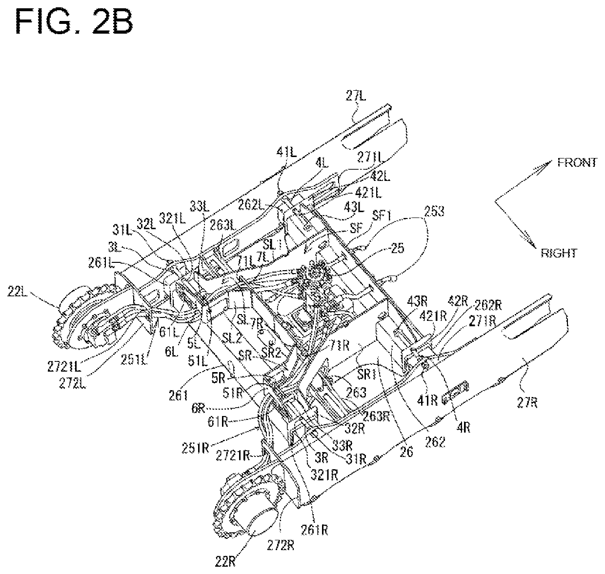
[0024]FIG. 1 is a left side perspective view of a backhoe 1 and illustrates the schematic configuration of the backhoe 1. The backhoe 1 includes a lower tr...


PUM


Abstract

A working vehicle has an upper rotating body and a lower traveling body. The lower traveling body is provided with: a center frame on which a swivel joint is vertically mounted; a right side frame on which a right traveling motor is mounted; a left side frame on which a left traveling motor is mounted; at least one right restriction member and at least one left restriction member, which restrict the maximum width of the vehicle; a right hose guide section having a right opening into which a right hydraulic hose is inserted, and provided to the right restriction member; and a left hose guide section having a left opening into which a left hydraulic hose is inserted, and provided to the left restriction member.

Description

TECHNICAL FIELD[0001]The present invention relates to a working vehicle, for example, a crawler type traveling working vehicle whose width can be changed.BACKGROUND ART[0002]Patent Literature 1 discloses a hydraulic hose piping structure of a mini shovel including a lower traveling body provided with left and right side frames that capable of changing the vehicle width. The hydraulic hose piping structure includes first and second restraining members that restrain first and second hydraulic hose groups connected between a center joint to left and right traveling devices, respectively, so that the hose groups are not dispersed.[0003]Patent Literature 2 discloses a hydraulic hose piping structure for a construction machine including a lower traveling body provided with left and right side frames capable of changing the vehicle width. In the hydraulic hose piping structure, first and second hydraulic hose groups connected between a center joint and left and right traveling devices, res...

Claims


Application Information

Patent Timeline
Patent Type & Authority Applications(United States)
IPC IPC(8): E02F9/02E02F9/08
CPCE02F9/024E02F9/0808E02F9/2275E02F3/964E02F3/325B60B35/1054B62D55/084B62D55/06E02F9/0858
Inventor HARADA, TAKAHIRO
Owner YANMAR POWER TECHNOLOGY CO LTD
Why Eureka
Try Eureka